PRESET THE OPENING PRESSURE OF THE
"EQUALIZER"
BEFORE INSTALLATION
CAUTION:
The opening pressure of the
"EQUALIZER"
should be preset with a purge gun (in the shop or field) prior
to installation on the divider block system. NOTE: To preset the Equalizer you must know the highest pressure
reading of the gauge on the discharge of the lubricator pump, with the compressor loaded.
Presetting the
EQUALIZER:
Adjust the pressure to open the
EQUALIZER
valve to a minimum of 300 PSI over the highest
pressure reading on the gauge at the discharge of the lubricator pump, with the compressor operating fully loaded.
After manually presetting the
EQUALIZERS
, install them in each tubing line of the divider block system.
NOTE:
After installing the
EQUALIZER
, you can make minor adjustments to ensure the pressure gauge pointer is
moving fluidly with no more that 200 PSI differential, with the compressor operating at max discharge pressure.
NOTE: ADJUST AND SECURE THE OPENING PRESSURE OF THE
EQUALIZER
PRIOR TO INSTALLATION ON THE
COMPRESSOR:
Tools needed: Manual purge gun, crescent wrench and 5/8" open end wrench.
NOTE:
The lock nut and adjusting nut on the
EQUALIZER
must be sealed with Torque Seal after adjusting the set pressure to
ensure the opening set pressure is secured and cannot be tampered with!
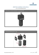
1. Connect purge gun to the
EQUALIZER
inlet and slowly pump oil through the unit.
(see fig 2)
2. As you're pumping oil into the
EQUALIZER
notice the pointer on the pressure gauge on the purge gun
to verify
(see fig 1)
pressure needed to pump through the unit.
3. Loosen the lock nut
with a 5/8" open end wrench and turn clockwise.
(see fig 3)
4. Increase opening pressure by rotating the adjusting nut clockwise.
(see fig 4)
5. Slowly pump oil through the
EQUALIZER
and continue visually checking the pressure on the purge gun gauge.
6. Continue turning adjusting nut clockwise
until the desired pressure setting is shown on the purge gun pressure
(see fig 4)
gauge.
7. Hand tighten the lock nut
to the adjusting nut,
then place a 5/8" open end wrench on the adjusting nut
(see fig 3)
(see fig 4)
for a backup. After opening pressure is set, Do Not allow the adjusting nut to rotate! If the adjusting nut is rotated, the pressure
desired settings will change. Tighten
to the secure pressure setting.
the lock nut securely with a 5/8" open end wrench
(see fig
3 & 4)
8. After you've set the
EQUALIZER
to the desired opening pressure, spread Cross Check Torque Seal over the adjusting nut
and lock nut.
If the torque seal has been broken at any time after the EQUALIZERS have been sealed. it's
(see fig 3 & 4)
obvious someone has tampered with the set pressure.
Adjusting Nut
on
"EQUALIZER"
Rotate to Increase
or Decrease Pressure
(fig 4)
LOCK NUT
(fig 3)
(fig 2)
INLET
PATTON
"EQUALIZER"
500
0
1000
1500
2000
2500
3000
3500
4000
II
I II
I
I
I
I
I
I
I
I
II
I I
I
I
I
I
I
I
I
I
II
I I I
L
U
B
R
I
C
A
T
O
R
P
R
O
D
U
C
T
S
(fig 1)
PRESSURE
GAUGE
EQUALIZER
Step 1
. Locate a convenient spot in the tubing between the divider block and the injection check valve. Cut out approximately
2 3/8" section of tubing.
Deburr the tubing ends to ensure metal particles do not get in the oil supply!
Caution:
Step 2.
Confirm the
EQUALIZER
is oriented with the arrow indicating direction of flow
from the divider block
(see fig 1)
towards the injection check valve and install the
EQUALIZER
in the tubing line.
Step 3.
Fully insert the tubing from the divider block
into the inlet of the
EQUALIZER
until it rests firmly on the
(see fig 2)
shoulder of the integral tube fitting.
(see fig 3)
Step 4.
Rotate the tubing cap (finger tight), then use
a backup wrench on the hex end of the
EQUALIZER
and
(see fig 5)
tighten each tubing cap one and one quarter turns to secure proper sealing at high pressure.
(see fig 6)
Step 5.
Repeat steps 4 & 5 for the outlet of the
EQUALIZER
, remember to fully insert the tubing to the shoulder of both tube
fittings.
(see fig 7)
(fig 7)
SHOULDER
(inside fitting)
(fig 2)
1/4" SS TUBING
(fig 1)
Direction of Flow
(fig 5)
HEX NUT
(fig 3)
SHOULDER
(inside fitting)
Outlet to Injection
Check Valve
From
Divider Block
(fig 6)
TUBE FITTINGS
Installing The
EQUALIZER
In The Tubing Lines Of The Divider Block System
3.750"