


1.0
INTRODUCTION
The purpose of this manual is to provide information for the installation, operation and maintenance of
the Model 1.8 MVSAT. Should any problems arise which are not discussed within this manual, such
problems should be referred to the equipment manufacturer:
Patriot Antenna Systems
704 North Clark Street
Albion, Michigan 49224 USA
Telephone: 517-629-5990
FAX:
517-629-6690
1.1 TECHNICAL DESCRIPTION
GENERAL
The Patriot 1.8 MVSAT system is a light weight, reliable system. The cable driven
system provides a near-zero backlash and highly reliable movement, all driven by a special
minimum / adjustable backlash gearbox powered by light, but rugged, DC drive motors. All drive
components are high strength steel in lightweight housings which result in the most reliable, stiff
system with the minimum of weight. The feed boom pivots at the elevation axis, allowing an option
of providing waveguide rotary joints on both the elevation and the azimuth axis. Also, pivoting the
feed boom at the elevation axis provides maximum space for a feed boom mounted amplifier or
transceiver. The Patriot Antenna System weighs only 220 lbs (100Kgs).
DRIVE SYSTEM
The drive system utilizes highly reliable aircraft control cables in a redundant configuration to
achieve a near-zero backlash, lightweight, very stiff drive system. It achieves this high tech
performance using low-tech components and simply wrapping the cable around the driver
capstan several times before wrapping the larger driven drum. The method used to wrap the
capstan results in a minimum length of free cable. The cables are pre-tensioned and spring
loaded at the main drum attachment point, eliminating backlash during antenna positioning.
SECONDARY DRIVE SYSTEM
The Azimuth and Elevation drive systems are driven by an adjustable cable, minimum
backlash worm gear set with a 40:1 ratio. The factory set and easily adjusted backlash of the
worm gear set is 1 – 2 arc minutes which is reduced further by the cable drive ratio resulting in
a backlash of only 0.005 degrees seen by the reflector system. Since the worm gear does not
back drive, an additional brake is not required on the motor. The worm-input shaft is extended
with a hex head end to allow manual deployment in case of power failure. Maximum gear
efficiency and minimum wear is achieved by sealing the gear sets in continuously lubricated
housings.
MOTOR DRIVES
Lightweight reliable servo quality DC motors with integral gearboxes are used for the Azimuth
and Elevation drive systems. These motors were selected because they provide the best
torque to weight ratio. Maximum reliability is achieved from the printed circuit armatures.
These motors produce constant torque over the speed range with uninterrupted travel at low
speeds, ensuring smooth operation during antenna peaking. The 18V DC design provides
current limiting torque control and will allow, if necessary, vehicle-battery powered operation.
The motors have their own weather tight covers but are covered with secondary covers to
assure maximum weather protection.
CONSTRUCTION
The trunnion, backing structure, feed booms and covers are all of aluminum construction.
Optional aluminum gear housings are available for minimum weight. Precision ground
bearings are used in all axes to assure long life and smooth positioning.
The reflector is a
carbon fiber composite sandwich construction manufactured in a multiple lay-up operation.
The lay-up mold surface provides the surface accuracy required for optimum performance.
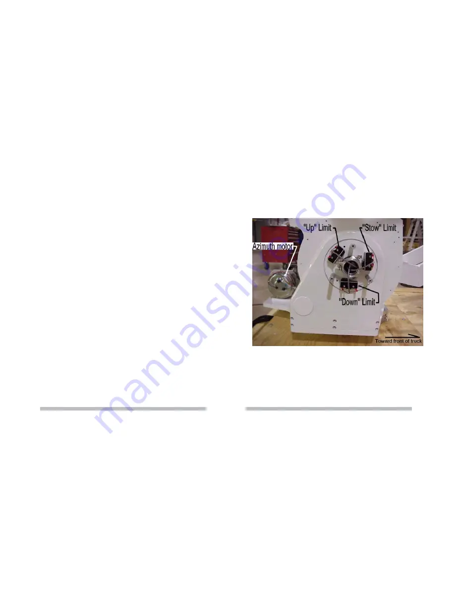
4.5 ELEVATION STOW AND LIMIT SWITCHES
If the antenna is mounted facing the front of the vehicle, remove the passenger side cover on the
elevation axis pivot shaft to gain access to the elevation stow, down and up limit switches. The switches
are fixed to reference ground (the elevation pivot blade) and are actuated by a cam on the rotating
elevation shaft. (Figure 4.4)
Figure 4.4
The elevation stow switch is actuated by the adjustable screw on the cam. It should be verified after
the system is installed on the truck so the reflector still clears the feed horn by approximately 1 inch.
Adjust the switch in small increments to allow for possible coasting of the elevation drive after power is
cut.
The elevation down limit switch is located at the 6 o’clock position. It rides up on the cam when the
elevation angle is below 5°. This prevents lowering the reflector / feed system below 5° until the
azimuth and polarization positioning systems are in their stow position.
The elevation up limit is located at the 10 o’clock position. It electrically terminates upward movement at
approximately 87°. The mechanical limit is 90° and may be achieved if desired by bending the actuator
slightly.
6
19


