


2.0 INSTALLATION AND SET-UP
2.1 GENERAL
The 1.8 MVSAT antenna has been fully tested with the controller
prior to shipment. All position feedback, limit sensing, limit switches and motors have been calibrated
or set. The installation involves securing to vehicle, connecting waveguide, installing LNB’s,
connecting coaxial cable, connection of control cables to controller and connecting auxiliary control
cable as necessary.
The vehicle roof should be reinforced with a substructure capable of handling the wind loads as
specified on the interface drawings for each size antenna.
A 12-inch diameter hole should be in the mounting surface. The mounting surface must be flat within
0.005 inch to prevent binding the azimuth bearing after torquing the mounting bolts. No obstruction
should be above the interface surface in a 20-inch diameter envelope. Any other roof-mounted
equipment such as air conditioners should be more than 92 inches from center of interface bolt
pattern.
The 16-inch diameter, 12-bolt pattern must be oriented properly with two bolts 15° on either side of the
centerline of the vehicle. Reference vehicle interface drawing for proper orientation.
2.2 INSTALLATION TO VEHICLE
Remove the top of the shipping crate. Remove the narrow side at the azimuth platform end of the
crate. Using the hand crank furnished, hand crank the elevation axis until the reflector support
structure is vertical.
Remove the bolts attaching the positioner to the shipping base. Adjust the forks on a fork lift to just
straddle the azimuth ring and under the elevation pivot assemblies.
Place cardboard pieces
between the positioner and the forks.
Carefully raise the antenna out of the crate and guide the control cables to prevent their catching on
the crate. Safety strap antenna to the fork lift truck. Remove the wooden antenna interface board from
the antenna. To serve as guides to position azimuth ring directly over the vehicle’s bolt circle, cut two
5/16-18 all thread rods to a length sufficient to allow protrusion into the vehicle interior for removal
once the antenna is seated into position. Grind one end of each rod to a rounded point to further help
guide antenna into the vehicle interface holes. Install these guides into holes diametrically opposed in
the antenna azimuth bearing. Maneuver the antenna to a position approximately two feet above the
vehicle interface.
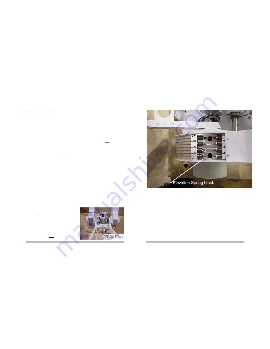
Note: Antenna must be installed with azimuth cable spring block aligned o
centerline of vehicle.
(Figure 2.1)
Figure 2.1
IF INTERFACE SURFACE IS
NOT FLAT
apply a thin layer of structural epoxy grout between azimuth
ring and vehicle surface. Thread control cables into the 12-inch diameter hole. Lower the antenna to
the antenna interface.
APPLY LOCKTITE 242 OR EQUIVALENT TO BOLTS,
install and snug bolts
finger tight. Allow epoxy to cure before final tightening.
IF INTERFACE SURFACE IS FLAT
APPLY A THIN COAT OF SILICONE BETWEEN AZIMUTH
RING AND SURFACE. Thread control cables into the 12-inch diameter hole. Lower the antenna to
the antenna interface.
APPLY LOCKTITE 242 OR EQUIVALENT TO BOLTS,
install and snug bolts
finger tight.
TIGHTEN ALL 12 BOLTS TO 18
-20 FT. LBS.
3 CONTROLLER INSTALLATION
Install controller into electronics rack. Connect P1 and P2 to J1 and J2. Note cables and jacks are
marked. Connect MS motor power cable to MS jack. Confirm voltage is correct. Connect AC power
cable to controller.
Figure 4.2
4.4 ELEVATION POSITION FEEDBACK
The elevation position feedback is produced by an electronic inclinometer. Since the drive has nearly
no backlash, the position feedback is as accurate as the resolution and accuracy of the inclinometer
The inclinometer has a resolution of 0.1 degrees with the accuracy / linearly of 1% in the 0 - 45° range
and monotonic in the 45 - 90° range. The inclinometer is rated for an outdoor environment. (Figure 4.3)
8
17


