EchoStar DISH 1000+, Installation Instructions Manual
The EchoStar DISH 1000+ is a cutting-edge satellite dish system that offers superior television reception. Ensure hassle-free installation with our comprehensive Installation Instructions Manual, available for free download from our website. Discover seamless setup and optimal performance by following this user-friendly manual.
Share
Download


Reviews:
No comments
Related manuals for DISH 1000+

500 FleetBroadband
Brand: Sailor Pages: 154

AT0300
Brand: ANTARION Pages: 18
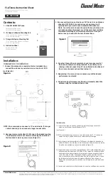
FLATenna
Brand: Channel Master Pages: 2
1.0 meter Back Pack Antenna
Brand: Patriot Pages: 12

Satmex 65 plus
Brand: camping first Pages: 27

ID ANT.U580/290-FCC
Brand: Feig Electronic Pages: 11

Value
Brand: MaxRange Pages: 7

AD900-9
Brand: Trango Systems Pages: 2

tracvision M7SK
Brand: KVH Industries Pages: 21

.90M
Brand: Patriot Pages: 16

Wireless Antenna
Brand: B&B Electronics Pages: 16

home FZ 45
Brand: Somogyi Pages: 11

202UK-0004
Brand: 1 BY ONE Pages: 2

VH226F
Brand: RCA Pages: 6

DIRECTV
Brand: RCA Pages: 48

DAT BOSS MIX
Brand: Televes Pages: 4

MM-3084
Brand: Winegard Pages: 8

SAS-543
Brand: A.H. Systems Pages: 13


