Patriot 1.0 meter Back Pack Antenna, Assembly Manual
The Patriot 1.0 meter Back Pack Antenna is a portable and lightweight solution for enhancing your communication capabilities. To ensure proper setup and usage, download the Assembly Manual for free from our website. Get the manual at manualshive.com and experience improved connectivity on-the-go.
Share
Download


Reviews:
No comments
Related manuals for 1.0 meter Back Pack Antenna
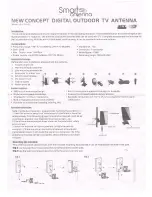
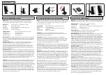
22-1-T711D
Brand: Smart Antenna Pages: 2
MCTV-970
Brand: Maclean Pages: 3
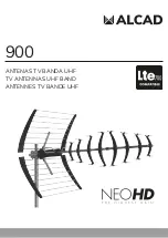
NEO-082
Brand: Alcad Pages: 7
Trav'ler Pro SK2SWM3
Brand: Winegard Pages: 12
928-042
Brand: Marquant Pages: 16
FLATenna
Brand: Channel Master Pages: 2
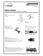
02MM-GX400
Brand: Matchmaster Pages: 2

15-248
Brand: Radio Shack Pages: 7

tracvision tv8
Brand: KVH Industries Pages: 51
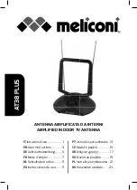
AT38 PLUS
Brand: MELICONI Pages: 28
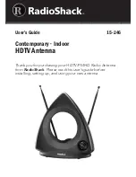
15-246
Brand: Radio Shack Pages: 6
Premium STV215
Brand: Bandridge Pages: 2
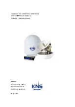
SUPERTRACK S4
Brand: KNS Pages: 81
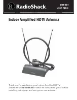
1500254
Brand: Radio Shack Pages: 8
DTA300
Brand: August Pages: 3
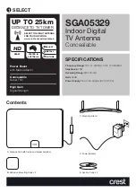
SGA05329
Brand: Crest Audio Pages: 4

TracVision TV5
Brand: KVH Industries Pages: 46

AT55 Black
Brand: MELICONI Pages: 28


