27
Wireless Data Communication System - WD PRO Series Instruction Manual
7. Operation
40 mm
Strip 6 to 7 mm
Cut
(about 30 mm)
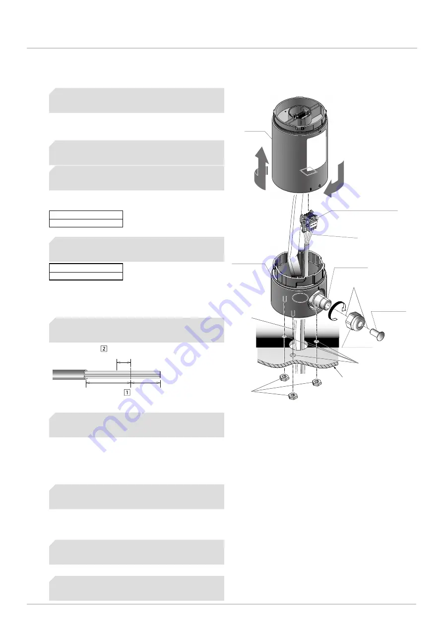
Terminal Block Connector
Body
Direct Mount
Bracket
Cable gland
Cap
Sealing plug
❷
❽
❺❼
❸
❻
❹
❶❾
(accessory)
(accessory)
(accessory)
7.1.1.1 Wiring RS-232C Cable from Bottom of Main Unit
40 mm
Strip 6 to 7 mm
Cut
(about 30 mm)
Terminal Block Connector
Body
Direct Mount
Bracket
Cable gland
Cap
Sealing plug
❷
❽
❺❼
❸
❻
❹
❶❾
(accessory)
(accessory)
(accessory)
☞ 7.1.3 Detaching the Terminal Block
In the mounting location, drill holes for mounting
and wiring the product.
❶
Rotate the body counterclockwise and detach
from the direct mount bracket.
❷
Apply the sealing plug and cap to the cable
gland, and rotate the cap clockwise to attach.
❸
Use nuts to secure the direct mount bracket in
the mounting position.
❹
Cut the RS-232C cable's lead wires so 40 mm
remains, then strip them.
❺
Pass the wires (gray or black) and RS-232C
cable through the wire distribution hole.
❻
Wire the RS-232C cable to the terminal block
connector and attach to the body.
❼
Attach the body to the direct mount bracket,
reversing the steps for detaching.
❽
If required, apply sealant around the mounting
and wire distribution holes.
❾
* When the sealing plug pops out of the cap, use your
hand to push the sealing plug back in.
* This illustration presents an overview of installation and
does not reflect the installation status at each step.
* RS-232C cable is not included.
* Maximum board
thickness: 7 mm.
☞ Mounting Hole Dimension Diagram(P.25)
* When using a pole bracket and pole, drilling holes is
unnecessary.
* When using a pole bracket and pole, refer to “7.1.1.4
Wiring Method When Using Pole Bracket and Pole
Recommended Torque
0.6 N•m (approximate)
Recommended Torque
0.6 N•m (approximate)
☞ 7.1.2 Replacing Mounting Bolts (M4 → M3) on the
* Do not secure when using a pole bracket and pole.


