


31
31
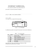
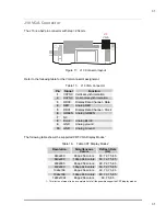
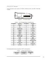
J10 VGA Connector
The J10 is a 5x2 pin connector with step =2.54 mm.
J10
VGA
Figure 17. J10 Connector layout
Refer to the following table for the VGA connector assignment.
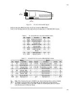
Table 15.
J10 VGA Connector
Pin
Signal
Function
1
VSYNC Vertical synchronization
2
HSYNC Horizontal synchronization
3
DDC0
Display Data Channel - Data
4
RED
Analog RED
5
DDC1
Display Data Channel - Clock
6
GREEN Analog GREEN
7
NC
8
BLUE
Analog BLUE
9
GND
Analog ground
10
GND
Analog Ground
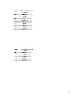
The following table shows the supported CRT-VGA Display Modes
1
Table 16.
Table CRT Display Modes
1
Resolution
Simultaneous
Colors
Refresh Rate
(Hz)
640x480
8bpp 256 colors
60, 72, 75, 85
640x480
16bpp 64K colors
60, 72, 75, 85
800x600
8bpp 256 colors
60, 72, 75, 85
800x600
16bpp 64K colors
60, 72, 75, 85
1024x768
8bpp 256 colors
60, 70, 75, 85
1024x768
16bpp 64K colors
60, 70, 75, 85
1280x1024
8bpp 256 colors
60, 75, 85
1.- This list is not meant to be a complete list of all the possible supported CRT display modes