


12
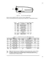
The following jumpers are located on the module:
One 3-pin jumper (JP5) for which there are only two possibilities:
¾
Connecting pin 1 to pin 2 (which will be indicated as 1-2)
¾
Connecting pin 2 to pin 3 (which will be indicated as 2-3)
Three 2-pin jumpers (JP1, JP7, JP8), which can be set as follows:
¾
Pin 1 connected to pin 2 (which will be indicated as
‘Closed’
)
¾
Pin 1 and pin 2 not connected (which will be indicated as
‘Open’
)
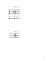
The following table provides a quick cross-reference for the SpacePC 1232 module’s jumpers.
Table 1.
Jumper Settings
PIN#
Type
Function
Default
JP1
2 pin
jumper
Write protection on Bios Flash
Closed: Write not allowed on Boot Block
Open: Boot Block can be written
Open
JP5
2 pin
jumper
Power Supply Source Selection for SSD Socket
1-2: Battery
2-3: VDD
2-3
JP7
2 pin
jumper
Invalid Setup
Open: Module starts with saved parameters
Closed: Module starts with default settings
Open
JP8
2 pin
jumper
External BIOS
Open: Module starts with internal BIOS (inside Flash EPROM)
Closed: Module starts with External BIOS
Open