


30
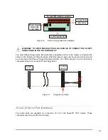
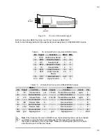
IDE Led
JP10
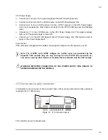
Figure 16. J9 and JP10 Connectors layout
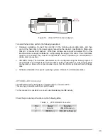
To install the hard disk, perform the following operations:
¾
Hardware installation.
Connect the hard disk to the module using a data cable, and then
connect the hard disk to the power supply respecting the device’s specifications. Make sure
that pin 1 of connector J9 and pin 1 of the drive or drives are correctly connected. Pin 1 of the
interface cable is usually indicated by a stripe along the edge of the cable. If two hard disks
need to be connected, they must be configured for common operation (i.e. master/slave or
cable select connection).
¾
IDE BIOS Setup.
The hard disk parameters can be configured using the Setup program. If
the hard disk is connected to the module without setup configuration or with a wrong setup
configuration, a time-out for a few minutes occurs, then the boot is performed from the floppy
disk.
¾
Software initialization for specific operating systems. R
efer to the OS documentation.
JP10 IDE LED Connector
The IDE HDD activity LED output is implemented on connector JP10.
This is a 2-pin connector with 2-mm pitch header.
To this connector is possible to connect a led that display the IDE activity.
Check the pin out and pin functions on the following table:
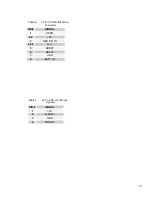
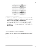
Table 14.
JP10 IDE LED Connector
Pin
Signal
Function
1
Ground
IDE LED anode (-)
2
IDELED (+)
IDE LED cathode (+)