background image

PAR POS Installation Manual for TACO DEL MAR


Page 

28 

system OFF and cut power to connected equipment loads. To ensure you hold the button for the 
correct length of time, do not release the button until you hear the UPS System’s audible alarm 
beep twice. The first beep occurs after one second and indicates that the UPS will turn OFF if the 
button is released. The second beep occurs after three seconds and indicates that the UPS will 
perform a self-test if the button is released.  

The test will last approximately 10 seconds as the UPS switches to battery to test its load capacity 
and charge. All LEDs will be lit and the UPS alarm will sound. See LED descriptions below to 
determine the results of the Self-Test.  

ON/OFF LED: 

This green LED lights continuously to indicate that the UPS is ON and supplying your equipment with 
AC power either from a utility source or from the UPSs internal batteries. If the UPSs alarm is 
sounding (4 short beeps followed by a pause), the UPS is operating from its internal batteries. 

Overload/Check Battery LED: 

This red LED lights continuously after a self-test to indicate the capacity of the battery-supported 
outlets has been exceeded. To clear the overload, unplug some of your equipment from the battery-
supported outlets; then use the ON/OFF/TEST button to run a Self-Test. If the UPS continues to 
detect an overload, remove more equipment and repeat the self-test until successful. 

CAUTION! Any overload that is not corrected by the user immediately following a self-test may 
cause the UPS to shut down and cease supplying output power in the event of a blackout or 
brownout.

 The LED flashes to indicate the battery needs to be recharged or replaced. If the LED 

flashes (and a continuous alarm sounds) during a prolonged blackout or brownout, the UPS’s 
batteries are nearly out of power; you should save files and shut down your equipment 
immediately. If the LED flashes following a UPS self-test (after the UPS is turned ON), it may indicate 
that the battery needs to be replaced. 

Allow the UPS to recharge continuously for 12 hours, then 

use the ON/OFF/TEST button to run a self-test. If the LED continues to flash, the unit needs to be 
replaced.


Содержание EverServ ES7700

Страница 1: ...PN 772231701 2013 ParTech Inc All rights reserved PAR POS Installation Manual for TACO DEL MAR ES7700...

Страница 2: ...y Corporation the parent company of ParTech Inc All other product names and services used throughout this material are trademarks or registered trademarks of their respective companies The product nam...

Страница 3: ...Connected to the Terminal 16 Gather the Cables and Replace Cable Retainers 16 Install Pedestal Cover and I O Panel 16 Connect POS Components to UPS 17 Power on the POS Equipment 18 Cleaning the POS Te...

Страница 4: ...reschedule your GoLive date please call our PAR Help Desk and ask to leave a message for a PAR GoLive Specialist Or you can send an e mail to the PAR_GoLive_Team partech com mailbox If you identify a...

Страница 5: ...help desk Tilt the head of the register back horizonally and lay the register on its back M3557 Tripp Lite Uninterruptible Power Supply M8570 03 Cash Drawer with Interface cable K4300 03 Netgear Rout...

Страница 6: ...ain pre installation guidelines are followed to protect your equipment your store and your employees If you have any questions regarding the following guidelines contact your PAR sales representative...

Страница 7: ...Customer Supplied and Supported WAP isolated from POS UPS Station 2 optional Station 1 Internet UPS optional Legend UPS Power Connection LAN Connection Other concept Internal Private Network UPS Plea...

Страница 8: ...acceptable bend radius cannot be straightened to correct a problem Cables should not be bent tighter than inch radius or about the size of a quarter Untwisting of pairs when making a termination shoul...

Страница 9: ...peripherals 1 Verify receipt and condition of all boxes and components Verify physical site and power availability is adequate 2 Verify the product numbers match the shipping list If it is not a match...

Страница 10: ...0 Remove the tape that is covering the cut out shown in figure 5 Figure 5 Pull the tape off the cut out You are now ready to begin setting up your terminal Remove Covers to Access Connection Panels NO...

Страница 11: ...n the pedestal and on the bottom of the pedestal for securing your cables in place to keep them neat and organized and prevent unintentional disconnection A cable retainer is located in the middle of...

Страница 12: ...e 5 Uncoil the telephone cable We will connect this to the UPS later 6 Next route the network cable down the pedestal and connect the cable to your router or switch Contact your high speed Internet pr...

Страница 13: ...ure 13 The wireless adapter will be plugged into the 12V USB port shown in Figure 14 Figure 13 Remove USB Dongle from wireless mouse Figure 14 Install USB Dongle 5 Install one AA battery for the wirel...

Страница 14: ...e printer Figure 16 Remove the tape from the printer cover 3 Follow the instructions on the inside of the printer cover to load the paper Figure 17 Load the paper 4 Close the printer cover 5 Locate th...

Страница 15: ...Up Network Connection If your store does not have a high speed connection to the Internet proceed to Connect Your Cash Drawer Cable to the POS 1 Connect your Ethernet cable to the network port on the...

Страница 16: ...ll act as a back up The diagram on the next page shows a typical configuration for LAN connections K4300 03 NETGEAR VPN Firewall LAN IP 192 168 0 1 Broadband Providers Modem Router WAP Configured as D...

Страница 17: ...23 Install the Cash Drawer Bracket 1 Locate the cable that is packaged with the cash drawer box part number C3506 Figure 24 M8570 03 Cash Drawer Figure 25 Cash Drawer Cable C3506 Figure 26 Cash Drawer...

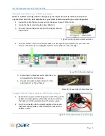
Страница 18: ...the top RJ 45 port COM port 1 on the POS terminal The RJ 45 port is highlighted yellow in the graphic on the next page Figure 29 RJ 45 port highlighted 5 Locate the coin dispenser serial cable that y...

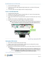
Страница 19: ...ace the cable retainer securing the cables neatly in place Ensure the cables are not kinked or stressed 2 Stand the POS upright on its base We will now connect your remaining POS peripherals Figure 33...

Страница 20: ...at this time 3 Plug the UPS into an electrical wall outlet 4 Connect the power cords for the terminal and printer into the battery backed outlets on the UPS 5 Press the on off test button and hold for...

Страница 21: ...our receipt printer and coin dispenser and DVD drive if present NOTE Your POS system may include hardware components that were not purchased from PAR For installation and service of such equipment con...

Страница 22: ...h sides and the nap has isopropyl alcohol cleaning solution on it The plastic card is passed through the reader like a credit card The MSR cleaning kit can be ordered from PAR by ordering part number...

Страница 23: ...3 You should see the following screen Figure 39 PAR GotoAssist Screen 4 If this screen appears then your internet is working on your new PAR system 5 If this screen does not appear try another website...

Страница 24: ...light icon 3 Verify prices in Price A column 4 To adjust price select item and click OK 5 Make changes to Price A field 6 Select to save any changes or click Close Form to exit Step 6 Add Owner to the...

Страница 25: ...rom the pull down menu 2 Click Receipt Setup 3 Verify the Receipt Header and Receipt Footer if applicable information is correct 4 Click the Hand with pencil icon to edit 5 Select to save any changes...

Страница 26: ...d operational Reference Page 10 and 11 for the M3873 61V Printer Installation instructions to make sure the printer is connected properly Figure 40 Epson Printer M3873 61V 2 Verify the printer paper i...

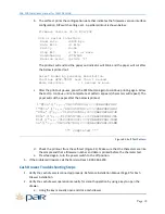
Страница 27: ...continue until a complete test pattern appears characters will repeat The paper will cut the paper after the below is printed 0123456789 ABCDEFGHI 0123456789 ABCDEFGHIJ X 0123456789 ABCDEFGHIJK 01234...

Страница 28: ...Exit to Sign In and Try Cash Drawer Again 4 If this doesn t correct the problem call Par Help Desk 1 800 382 6200 Register Troubleshooting 1 Press the black power switch located in the left corner un...

Страница 29: ...ght inward for a positive connection Figure 45 AC power cord left DC power cord right Power Button b Check the AC power cord connection at the power brick 4 Verify the register AC power cord is connec...

Страница 30: ...ge Protected Outlets right CAUTION The UPS is designed to support electronic equipment only The UPS will be overloaded if the total VA ratings for all the equipment you connect to the Battery Backup S...

Страница 31: ...from its internal batteries Overload Check Battery LED This red LED lights continuously after a self test to indicate the capacity of the battery supported outlets has been exceeded To clear the over...

Страница 32: ...PAR Phone Numbers For Service USA and CANADA 800 382 6200 For Parts USA and CANADA 800 PAR PART For Sales Continental USA except New York 800 448 6505 Outside Continental USA 315 738 0600...

Отзывы: