Parker Sporlan Subcool Control Скачать руководство пользователя страница 6

Page 6 

– Bulletin 100-50-5.2

Recommended Network Configuration:

 Daisy Chain, a 

single continuous transmission line from one end to the other. 
Other configurations involving triple-lug connections, such as 
star, are not recommended. See Figure 3.

Addr

 - 

The address of the controller on the MODBUS net-

work. See Section 3 - Setpoint Menu Operation to change it.

Noise Reduction:

 Termination resistance (

R

T

 in Figure 4) 

is recommended to reduce reflections and noise on the data 
transmission lines. Place the resistance at the extreme


ends of 

the cable with the resistance value matching the characteristic 
impedance of the transmission line (typically 120 ohms for 
twisted pair cables).

Shielding prevents noise from EMI sources. If the cable is 
shielded, connect the shield to earth ground at one end only. 
Do not connect shield to RS485 GND.

Keep RS485 wiring away from high voltage AC lines to 
reduce noise and data errors on communication lines. RS485 
communication cable should be perpendicular to AC lines at 
any intersection.

Grounding:

 Connect a third conductor to RS485 GND (pin 13) 

to prevent ground potentials from node to node. This conduc-
tor should be included in the shield of the twisted pair cable to 
prevent noise. Do not connect RS485 GND to earth ground.

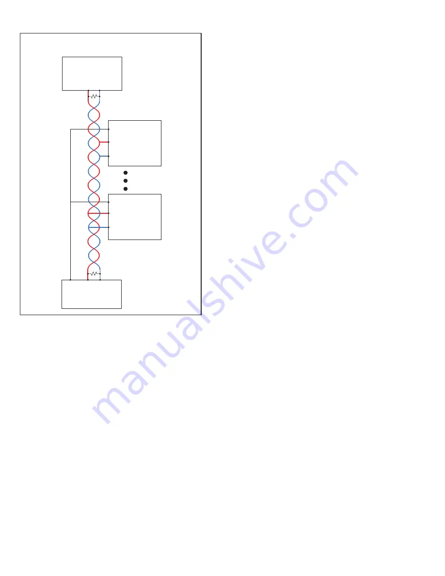
Figure 4 - Modbus Wiring

Controller 1

GND

R

T

R

T

Communication

Master

A     B

B

Controller n

R

T

Termination 

resistor

B

A

Controller n-1

GND

B

A

A

GND

Third Party Controllers:

 To avoid nuisance “network errors”, 

the use of third party controllers on the same RS485 network 
with Sporlan controllers and master is not recommended. If 
necessary, use a separate communication board on the master 
to connect separate third-party controllers.

See Appendix K - MODBUS Memory Map, page 17. Also, 
refer to the documentation supplied with the communication 
master for additional RS485 network requirements.

6. PID Tuning

The Sporlan Subcool Control is factory programmed with de-
fault Proportional–Integral–Derivative (PID) settings that will 
provide efficient control. It may be necessary, however, to fine 
tune the PID settings in applications where systems experi-
ence rapid transient conditions (such as frequent “impulse” 
changes in loading or mass flow rates).

The controller offers PID adjustments for both Subcooled 
liquid temperature and Superheat control. In most instances, 
adjustments to the PI set-points are adequate. If tuning is 
needed, see Section 3 - Setpoint Menu Operation to enter 
the PID setpoint menu. The following guidelines should be 
followed:

• 

Lp

 (Liquid Proportional Coefficient) – Increase value to in-

crease valve response to Subcooled liquid out temperature.

• 

Li

 (Liquid Integral Coefficient) – Increase value to 

decrease valve response to Subcooled liquid out tempera-
ture over a given time period.

• 

Ld

 (Liquid Derivative Coefficient) – Increase value to 

increase valve response to rate of change in Subcooled 
liquid out temperature.

• 

Sp

 (Superheat Proportional Coefficient) – Increase value 

to increase valve response to Superheat.

• 

Si

 (Superheat Integral Coefficient) – Increase value to 

decrease valve response to Superheat over a given time 
period.

• 

Sd

 (Superheat Derivative Coefficient) – Increase value to 

increase valve response to rate of change in Superheat. 

•  LSHi 

(Low Superheat Integral Coefficient) – Increase 

value to decrease valve response to superheat over a given 
time period (Only in low Superheat conditions).

If PID adjustments are made, allow adequate time for the sys-
tem to respond to the changes. 

Large oscillations in Subcooled liquid or Superheat may require 
adjustments to the respective PID values. If Subcooled liquid 
and Superheat are equally unstable, adjust the Superheat PID 
values first, followed by the liquid PID values.

• 

When the Superheat is oscillating to extremes, the Propor-
tional value may be too high and/or the Integral value may 
be too low. 

• 

If the Superheat is not oscillating to extremes, but the 
Liquid control is very inconsistent around setpoint, then the 
Proportional value may need to be reduced or the Integral 
value increased.

Содержание Sporlan Subcool Control

Страница 1: ...Bulletin 100 50 5 2 Page 1 Subcool Control Installation and Operation Instructions July 2020 Bulletin 100 50 5 2 Controller v G 1...

Страница 2: ...e The user through its own analysis and testing is solely responsible for making the final selection of the system and components and assuring that all performance endurance maintenance safety and war...

Страница 3: ...ressure temperature control for most common refrigerants It displays actual leaving liquid temperature superheat suction pressure valve position controller status and alarms It also allows manual cont...

Страница 4: ...ivity and you will lose all changes entered 1 Enter the Parameter Menu Press and hold the SELECT knob for 5 seconds Rotate the knob to enter the pass word 111 and press the SELECT knob again 2 To chan...

Страница 5: ...ges Ensure superheat does not drop below that described above To exit manual operation mode press encod er knob scroll to ESC and press the knob again After exiting manual mode observe the system for...

Страница 6: ...ammed with de fault Proportional Integral Derivative PID settings that will provide efficient control It may be necessary however to fine tune the PID settings in applications where systems experi enc...

Страница 7: ...nsor will read 60 on the controller Temperature sensor output can be checked by measuring the DC voltage across the sensor wire using the tables in Appen dix L page 19 and Appendix M page 20 Since the...

Страница 8: ...ontrol power Pump down signal ensure Subcool Control expansion valve is not closed Proper system refrigerant charge Liquid line filter clogging or excessive pressure drop Proper Subcooler OffTemperatu...

Страница 9: ...adout Description R 22 R 134a R 402A R 404A R 407A R 407C 410A R 410A 417A R 417A R 422A R 422D R 507A R 744 R 245FA R E5 R 438A R 401B 408A R 408A 508A R 508A 508B R 508B 407F R 407F 434A R 434A 444B...

Страница 10: ...ional S 4 Status of the Auxiliary Temperature Input Stat Controller Status ALS Controller Alarms APPENDIX C Controller Status DISPLAY DESCRIPTION CooL Subcool On Valve modulating pdn Pumpdown Valve cl...

Страница 11: ...448A R 448A 450A R 450A 449A R 449A 452A R 452A 513A R 513A Maximum Valve Capacity 0 to 100 Default is 100 Liquid Proportional Coefficient 0 to 25 5 Default is 1 0 Increase value to increase valve res...

Страница 12: ...Units Readout Description Pounds Force Per Square Inch Bars Temperature Units Readout Description Fahrenheit Celsius t4p Temperature SensorType Readout Description typ3 3k typ2 typ2 2k tP10 10k 4 Cho...

Страница 13: ...Coefficient LSHi Low Superheat Integral Gain Coefficient The integral gain coefficient to use for the superheat PID loop if the superheat is below 3 degrees F CyCt CycleTime The PID update time StEP...

Страница 14: ...ENDIX G Alarms and Failsafes APPENDIX H Technical Specifications ELECTRICAL Supply Voltage 20 26VAC 50 60Hz or 22 26 6VDC Class II input 40VA is recommended for each controller Digital Inputs 0 5VDC M...

Страница 15: ...ls Counter Flow Brazed Plate Heat Exchanger Dry Contacts T4 Evap Outlet Temp T1 Liquid Outlet Temp T2 White Signal Green Ground Black 5VDC Black 24V AC DC RS485 White Green Red B Ground A Suction Temp...

Страница 16: ...ensors 10 14 inches from the heat exchanger on a free draining hori zontal line 2 Remove all insulation and adhesives at the marked loca tion Using Scotch BriteTM clean the copper line to remove oxide...

Страница 17: ...422D 10 R 507A 11 R 744 12 R 245FA 13 R E5 14 R 438A 15 R 401B 16 R 408A 17 R 508A 18 R 508B 19 R 407F 20 R 434A 21 R 444B 22 R 448A 23 R 450A 24 R 449A 25 R 452A 26 R 513A 5 Valve Maximum 0 to 100 6...

Страница 18: ...sor Range and Type 15 to 500 PSI 1 01 to 34 47 Bar Maximum Range 4 Saturation Temperature 60 to 150 F 51 1 to 65 6 C 5 Suction Temperature 60 to 125 F 51 1 to 65 6 C 6 Valve Position of Max Stroke 0 t...

Страница 19: ...5 0 41 1 837 1 915 5 6 42 1 812 1 889 6 1 43 1 788 1 863 6 7 44 1 763 1 837 7 2 45 1 739 1 812 7 8 46 1 715 1 787 8 3 47 1 691 1 763 8 9 48 1 668 1 738 9 4 49 1 644 1 714 10 0 50 1 621 1 690 10 6 51 1...

Страница 20: ...698 5 0 41 2 556 2 663 5 6 42 2 522 2 628 6 1 43 2 489 2 593 6 7 44 2 455 2 558 7 2 45 2 422 2 524 7 8 46 2 389 2 489 8 3 47 2 356 2 455 8 9 48 2 323 2 421 9 4 49 2 290 2 386 10 0 50 2 258 2 353 10 6...

Страница 21: ...438 3 540 15 0 59 3 412 3 511 15 6 60 3 383 3 486 16 1 61 3 357 3 456 C F RANGE VDC 16 7 62 3 327 3 427 17 2 63 3 301 3 401 17 8 64 3 271 3 372 18 3 65 3 244 3 346 18 9 66 3 214 3 316 19 4 67 3 183 3...

Страница 22: ...een 98 6k Surface Sensor white 952662 230545 230546 230072 230076 230078 230073 952565 Used with or without well 20 ft Surface only 20 ft Air Only 20 ft Surface only 20 ft Surface only 20 ft Surface o...

Страница 23: ...ion Author Approved 000 122011 Added Revision History 001 062012 Updated Appendices E I K N Updated Table 2 JH ER 002 112012 Revised as Bulletin JH ER APPENDIX P System Flow Chart Start NO PROCESS Con...

Страница 24: ...Parker Hannifin Corporation Sporlan Division 206 Lange Drive Washington MO 63090 USA phone 636 239 1111 fax 636 239 9130 www sporlan com Bulletin 100 50 5 2 72020 2020 Parker Hannifin Corporation...

Отзывы: