Parker PowerStation XT Series Скачать руководство пользователя страница 32

PRODUCT OVERVIEW 

32

   Parker XT/IX/PCA PowerStation User Manual  
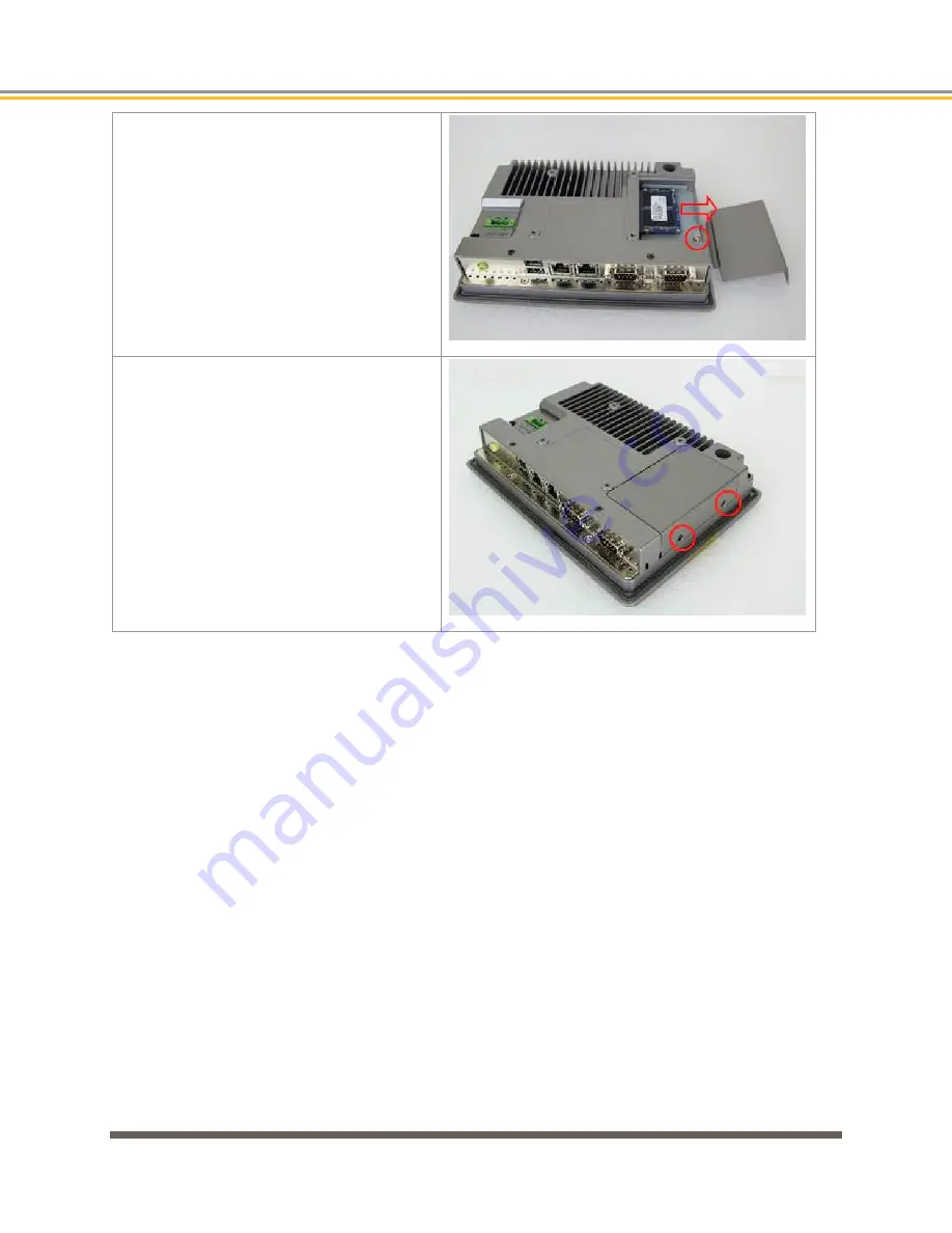
Step 2 

To remove the SSD bracket assembly, 

remove the retaining screw as shown and 

then carefully pull bracket in the direction 

shown to unplug the assembly from the 

chassis. 


Step 3 

Reverse steps 1 and 2 above to replace the 

SSD bracket assembly and cover onto the 

chassis. 


Содержание PowerStation XT Series

Страница 1: ...PARKER XT IX PCA PowerStations User Manual 2018 Parker Hannifin Corporation All Rights Reserved ...

Страница 2: ...s a registered trademark of 3S Smart Software Solutions GmbH Windows is a registered trademark of Microsoft Corporation SD is a trademark or registered trademark of SD 3C LLC in the United States other countries or both Acronis is a registered trademark of Acronis International GmbH Intel is a trademark of Intel Corporation in the U S and or other countries ...

Страница 3: ... are not designed or intended for any use in any systems machines or applications where failure or fault of any kind of the Products could reasonably be seen to lead to death or serious bodily injury of any person or to severe physical or environmental dama permitted to use distribute or sublicense the use of these Products in High Risk Use High Risk Use is STRICTLY PROHIBITED WARNING XT IX PCA Po...

Страница 4: ... the application are met The user must analyze all aspects of the application follow applicable industry standards and follow the information concerning the product in the current product catalog and in any other materials provided from Parker or its subsidiaries or authorized distributors To the extent that Parker or its subsidiaries or authorized distributors provide component or system options ...

Страница 5: ...2 2013 2014 30 EU Electromagnetic Compatibility when installed operated and maintained as intended FCC Statement of Compliance Product Type XT IX PCA PowerStations Industrial HMI and PC Products Warning This equipment has been tested and found to comply with the limits for a Class A digital device pursuant to part 15 of the FCC Rules These limits are designed to provide reasonable protection again...

Страница 6: ...tallation the product must meet the following criteria Input power is rated at 12 VDC or 24 VDC 15 25 SELV Limited Energy External power to the PowerStations must be provided by a Class 2 power source For customer convenience Parker offers an AC input Model PS 60W Class 2 24VDC power supply which is available for purchase Note XT IX PCA PowerStations have been evaluated to UL61010 2 201 and compli...

Страница 7: ... and II Division 2 and Class III Divisions 1 and 2 Hazardous Classified Locations Installation in Hazardous Locations must adhere to the following installation guidelines 1 THESE DEVICES ARE OPEN TYPE DEVICES AND MEANT TO BE INSTALLED IN AN ENCLOSURE SUITABLE FOR THE ENVIRONMENT SUCH THAT THE EQUIPMENT IS ONLY ACCESSIBLE WITH THE USE OF A TOOL 2 SUITABLE FOR USE IN CLASS I DIVISION 2 GROUPS A B C ...

Страница 8: ...s Unit Only 29 SD Card 29 Solid State Drive SSD 31 CHAPTER 2 Installation 33 Checking the Shipment 34 Installation Guidelines 35 Unit Installation 38 Headless Unit Basic Installation Steps Panel Mounting 38 Touchscreen Units Basic Installation Steps Panel Mounting 39 Display Based Units Basic Installation Steps VESA Mounting 41 Attaching Cables 43 CHAPTER 3 Software 47 XT PowerStation Configuring ...

Страница 9: ...SD 81 Parker Flashback Utility 81 IX PCA PowerStation Restoring the Solid State Drive SSD 83 F11 Disk Image Recovery Procedure 83 Using Acronis to Create your Own Backup Image 85 How to obtain Technical Assistance from Parker Hannifin 86 APPENDIX A XT IX PCA PowerStation Specifications 89 Environmental Specifications 90 Electrical Specifications 90 Display Specifications 91 Agency Approvals 92 Phy...

Страница 10: ...ttp www parker com emn PC Assumptions of Technical Experience Parker Hannifin Corporation assumes you are qualified in the servicing of industrial control systems and trained in recognizing hazards in products with hazardous energy levels To install and troubleshoot XT IX PCA PowerStations you should have a fundamental understanding of the following Electronic concepts such as voltage current and ...

Страница 11: ...seful WARNING A warning provides information about a potential for property damage personal injury or death CAUTION A caution provides information intended to help prevent malfunction of the product or damage to the product hardware or software NOTE A note provides information intended to help you make the best use of your product from Parker Hannifin Corporation ...

Страница 12: ......

Страница 13: ...CHAPTER 1 Product Overview ...

Страница 14: ...tems and build up different models as needed significantly reducing lead times The main difference between each series is the functionality of each unit dictated by the software Other major differences include the storage type and operating systems needed to support those software platforms XT Series IX Series PCA Series Storage 2 GB SD Card 64 GB SSD 64 GB SSD Operating System Windows Embedded Co...

Страница 15: ...ries PowerStation products with Interact Xpress HMI can be used as a runtime only system which means that applications and projects can be created on a development PC and the Xpress HMI application can be downloaded to the PowerStation In addition applications using the Interact Xpress HMI software can be created or changed directly on the XT unit itself or remotely from anywhere via an Internet b...

Страница 16: ...Server Runtimes can communicate with any OPC Servers for motion controllers temperature controls etc Bundled Communications Drivers The integrated COMM Server includes communications drivers including serial and Ethernet drivers for the major controller brands ActiveX Automation Microsoft applications such as Excel Access VB or C programs can Automation Multi Language Support The Designer and Runt...

Страница 17: ...port12 24VDC input power resistive and capacitive touchscreen options and an IP65 compliant front panel No Display Headless 7 0 wide format display options Flat front panel resistive touch screen Fanless design Intel Bay Trail N2930 1 83GHz Quad Core CPU Onboard 4GB DDR3L 1600 MHz 2GB SD Card or 64GB SSD solid state storage options 12VDC 24VDC auto ranging power input IP65 compliant front panel Fi...

Страница 18: ...he XT IX PCA can be mounted as a free standing station using the VESA mounting holes located on the back of the units See Unit Installation for further information Figure 1 3 External Port Locations The following sections describe the functionality of these ports Serial Ports COM1 COM2 The XT IX PCA PowerStations have two serial ports that you can use to communicate with external devices at baud r...

Страница 19: ...immunity than RS 232 These standards increase the maximum cable length to 4 000 feet 1 200 meters RS 422 communications are full duplex send and receive simultaneously while RS 485 communications are half duplex send or receive independently For either configuration be careful not to connect any wires to unused connector pins Information on the specific connection required for the InteractX driver...

Страница 20: ...at must be configured to set the desired communications method Configure both the hardware switch settings below S_422 and S_232 Switch Settings AND make the corresponding BIOS setup selection in the Advanced settings tab Advanced F81216 Super IO Configuration Serial Port 1 Configuration RS 232 is the default communication method Caution Failure to set both the S_422 and S_232 Switch Settings outl...

Страница 21: ...igured as shown in the table below JP1 is a 2x3 Pin Header located on the motherboard and can be accessed by removing the rear cover of the unit Refer to the diagram below for its location on the motherboard JP1 Pin Function Close 1 2 COM1 Pin 9 RI Ring Indicator default Close 3 4 COM1 Pin 9 5VDC option Close 5 6 COM1 Pin 9 12VDC option ...

Страница 22: ... bracket assembly if installed to access the switches NOTE Also Refer to BIOS Setup selection Advanced F81216 Super IO Configuration Serial Port 1 Configuration in addition to the following switch settings to set the communications mode of this port Function S_422 Switch Setting S_232 Switch Setting RS232 Default OFF SW 1 SW 2 SW 3 SW 4 SW 5 ON SW 1 SW 2 SW 3 SW 4 SW 5 RS422 option ON SW 1 SW 2 SW...

Страница 23: ...n 8 CTS Clear To Send Pin 9 RI Ring Indicator Default Set JP2 on motherboard to select RI 5V or 12V COM2 Pin 9 Output Motherboard Jumper Setting JP2 Pins 1 6 are used to select signal output type of pin 9 of the COM2 port and can be configured as shown in the table below JP2 is a 2x3 Pin Header located on the motherboard and can be accessed by removing the rear unit enclosure Refer to the diagram ...

Страница 24: ...Station it is important to note that the XT IX or PCA serial port pinouts differ from the legacy products Although the connector types are all standard male DB 9M style physical connectors the port designations and cable wiring between the two products vary slightly XT IX PCA PowerStation Example COM1 Connector Pinouts and Cable Wiring RS 232 RS 422 RS 485 XPR2 XPC2 EPX2 PowerStation Example COM2 ...

Страница 25: ...M2 Pin 1 DCD Data Carrier Detect NC DCD 422_RX 422_TX 422_TX NC 485 485 Pin 2 RXD Received Data RXD RXD 422_RX 422_TX 422_RX NC 485 NC Pin 3 TXD Transmit Data TXD TXD 422_TX 422_RX 422_TX 485 NC 485 Pin 4 DTR Data Terminal Ready NC DTR 422_TX 422_RX 422_RX 485 NC NC Pin 5 Ground Ground Ground Ground Ground Ground Ground Ground Ground Pin 6 DSR Data Set Ready NC DSR NC NC NC NC NC NC Pin 7 RTS Requ...

Страница 26: ... Ring Indicator Default Set JP2 on motherboard to select RI 5V or 12V RI RI Caution Please note the following differences between the new and legacy products Both products have a single configurable RS 232 RS 422 RS 485 communications port COM1 on the new models and COM2 on the legacy models Pinouts between the new and legacy models differ slightly please refer to the Cable Wiring examples and pin...

Страница 27: ...e unit is OFF the green Power LED is extinguished momentarily closing the switch for about 2 3 seconds will allow the system to begin booting into the Windows operating system WES7P and Windows 10 can also enter a hibernate state by holding the switch closed for approximately 1 second Once in this state pressing the switch again for approximately 1 second will awake the unit from hibernation Note ...

Страница 28: ...terface cable is highly dependent on the quality of the cable and the resolution of display image In general budget cables should perform well if they are no longer than 15 to 25 feet and depending on the quality of the cable and desired resolution may function well to 50 feet NOTE As analog video cables increase in length the available bandwidth decreases and with it the highest potential display...

Страница 29: ...out at 1024x768 video resolution without distortion pixilation or artifacts If the application requires a video cable exceeding 10 feet in length we recommend that the specific cable type and length be tested in the intended application to insure proper visual operation Video extenders are available in the market to extend the distance between the PowerStation and a monitor in excess of 4000 feet ...

Страница 30: ...n an XT PowerStation the SD Card must be formatted as a bootable card Simply copying Parker HMI files to a commercial SD card may not allow the card to function properly See the section Parker Flashback Utility for reimaging the SD card Refer to the following illustrations for locating the SD Card connector on the various PowerStation model sizes ...

Страница 31: ...rStation models are supplied with a 64GB SSD The drives are formatted and loaded with the operating system and application software from the factory See F11 Disk Image Recovery Procedure for information regarding reimaging the SDD Installation Removal of SSD Module In the event that the SSD module needs be removed or replaced follow these steps Step 1 Remove two screws to remove access cover ...

Страница 32: ...p 2 To remove the SSD bracket assembly remove the retaining screw as shown and then carefully pull bracket in the direction shown to unplug the assembly from the chassis Step 3 Reverse steps 1 and 2 above to replace the SSD bracket assembly and cover onto the chassis ...

Страница 33: ...CHAPTER 2 Installation ...

Страница 34: ...erStations only 88 026691 01 Installation Safety Requirements The XT IX PCA family of PowerStations meet the requirements of the Electromagnetic Compliance EMC directive 2004 108 EC EN55022 EN55024 when installed according to the instructions provided in this chapter WARNING XT IX PCA PowerStations connect to other mechanical and electrical components of your system Be sure to test your system for...

Страница 35: ... OPEN TYPE DEVICES AND MEANT TO BE INSTALLED IN AN ENCLOSURE SUITABLE FOR THE ENVIRONMENT SUCH THAT THE EQUIPMENT IS ONLY ACCESSIBLE WITH THE USE OF A TOOL 2 SUITABLE FOR USE IN CLASS I DIVISION 2 GROUPS A B C AND D HAZARDOUS LOCATIONS OR NONHAZARDOUS LOCATIONS ONLY TEMPERATURE RATING T5 3 WARNING EXPLOSION HAZARD DO NOT DISCONNECT EQUIPMENT WHILE THE CIRCUIT IS LIVE OR UNLESS THE AREA IS KNOWN TO...

Страница 36: ...werStation with its 50 ºC operating temperature limit into a sealed enclosure without considering the effects of the internal heat buildup Since elevated operating temperatures can have an adverse effect on the life of electronics it is wise to consider the internal thermal rise Passive venting for thermal convection internal air circulation fans filtered exhaust fans with filtered inlets air cond...

Страница 37: ...d by utilizing Pin 3 on the input power connector This connection must be made with the shortest possible heavy gage wire or braided cable Low resistance 0 5 ohms continuity should be verified with an ohmmeter for proper grounding In addition all communication cables should be shielded and grounded preferably only on one end Earth Grounding Guidelines To minimize unwanted electrical interference s...

Страница 38: ...resent against the items listed in the table at the beginning of this chapter Checking the Shipment 2 Once a suitable mounting location has been selected mark the screw hole locations on the enclosure panel using the Headless Mounting Pattern dimensions below See also Physical Dimensions and Panel Cutouts in Appendix A Four 6 or M3 5 screws or bolts are required to mount the unit to the panel The ...

Страница 39: ... the cutout edges are free of burrs and smooth to allow for proper sealing of the perimeter gasket The dimensional tolerance for each cutout is 0 02 0 5 mm Display Size Panel Mounting Cutout Dimensions 7 0 259 5 mm 3 Slide the unit into the cutout and attach the supplied mounting clamps with their screws to the perimeter of the unit in the slots provided as shown in the illustration below Tighten ...

Страница 40: ...al Fig 2 1 Panel Mounting Diagram 4 Connect any Ethernet network cables depending on the installation Refer to Attaching Cables later in this section 5 Connect 12VDC or 24VDC power to the PowerStation by following the precautions described in Connecting Power later in this section ...

Страница 41: ...PowerStation is either 75mm x 75mm or 100mm x 100mm depending on the display size For the location of the VESA mounting holes see Physical Dimensions and Panel Cutout in Appendix A Display Size VESA Mounting Pattern Dimensions Headless 100mm x 100mm 7 0 75mm x 75mm 100mm x 100mm 100mm x 100mm 100mm x 100mm WARNING Be sure to not exceed the load weight specifications supplied with the mounting arm ...

Страница 42: ...ual Fig 2 2 VESA Mounting Diagram 3 Connect any Ethernet network cables depending on the installation Refer to Attaching Cables later in this section 4 Connect 12VDC or 24VDC power to the PowerStation by following the precautions described in Connecting Power later in this section ...

Страница 43: ...hannel length is 100 meters or 328 feet Either straight through or crossover patch cables may be used since the PowerStation will auto detect and adjust to the type of cables used The cable must not be kinked or bent too tightly the bend radius should be no less than four times the outer diameter of the cable Either shielded or unshielded cables may be used Consider using shielded cables in electr...

Страница 44: ...arth Ground The system input power rating for the various unit display sizes are Display Size Maximum Input Power Required Headless 24 W max 7 0 23W max 25W max 32W max 37W max The following is the recommended wire gage for connection to the PowerStation power input connector 0 20 1 0 mm IEC 26 16 AWG UL stripped to 10mm in length solid or stranded wire Connection Diagram For convenience the input...

Страница 45: ...Fig 2 3 Input Power Connection Diagram CAUTION Do not apply AC line input power directly to the PowerStation or damage may occur Nominal 12VDC or 24VDC 0VDC Earth Ground ...

Страница 46: ...C machine power is not available CAUTION Do not apply AC line input power directly to the PowerStation or damage may occur Mounting the Optional PS 60W AC Power Supply The optional PS 60W AC power supply is DIN rail mountable To reduce issues associated with noisy DC power input keep the 24VDC wiring away from any AC interfering sources such as motor leads or other devices Refer to the PS 60W or t...

Страница 47: ...CHAPTER 3 Software ...

Страница 48: ...the factory with Interact Xpress HMI software and a demo application already installed Once the custom application or project has been developed on a PC or laptop computer there are two ways to download it to the XT PowerStation SD card via an Ethernet project transfer or copy the application directly to the SD card using a card reader The first time you power up the unit you may need to change th...

Страница 49: ...r in the upper left hand corner with a red dot in the middle of the circle Use your finger or stylus to touch and hold in place until the circle goes away This process will repeat for each of the corners of the screen After the fourth corner calibration is complete To skip the procedure do not press the touchscreen for a few seconds to allow the software to timeout or press using an attached keybo...

Страница 50: ...0 Note Disabling the network connection through a remote browser results in a loss of connection which can only be restored locally Dynamic Select the Dynamic radio button to allow the local machine to automatically go out and request for an IP address from the server This IP address then is used to identify this unit on a network All of the information IP address subnet mask etc is displayed but ...

Страница 51: ...le the Proxy Server address and port settings The Proxy Server forwards requests from the unit to other servers The server retrieves data from remote web servers Proxy Address Enter the IP address or the name of the proxy server The name can be up to 15 characters long Proxy Port Enter the port number of the proxy server The number can range from 80 to 9999 with the default set to 80 Click OK to a...

Страница 52: ...ctX Development software Running InteractX 4 0 Software on IX Hardware Creating a New Project A new InteractX project running on the IX hardware will look best if the specific screen resolution of the hardware is considered when building panels The resolution of the IX hardware is different depending on the screen size Screen Size Resolution IXx 007 7 0 800 x 480 IXx 010 10 1 1280 x 800 IXx 015 15...

Страница 53: ...As you create panels they will now show what will appear on the IX hardware ...

Страница 54: ...e procedures The IX and PCA could have a Resistive touchscreen or a Capacitive touchscreen depending on how it was ordered from the factory There are different calibration procedures depending on the type of touchscreen As shipped from the factory and after using the F11 to restore a facory image there are two shortcuts on the desktop for quick access to the calibration utilities One is for resist...

Страница 55: ......

Страница 56: ...Manual When the Device 0 window appears click to start calibration procedure Capacitive Touchscreen Calibration eGalaxTouch Calibration of the capacitive touchscreen can be performed within the eGalaxTouch utility which can be launched from the Start Menu ...

Страница 57: ...axTouch and Configure Utility A white calibration screen will appear Using a plastic pointer stylus or your finger touch hold and lift off the 4 calibration targets precisely in the center as they appear An ...

Страница 58: ...ftware is licensed to run for a short period of time in an evaluation mode only InteractX will function for one hour for demo and evaluation purposes and can be licensed by the user by contacting Parker Support Because Microsoft WES7P or Windows 10 software may be installed and operated by the user The touchscreen calibration procedure is the same as with the IX PowerStation ...

Страница 59: ...CHAPTER 4 BIOS Setup ...

Страница 60: ...up Utility After CMOS battery discharge a BIOS flashing operation or to change BIOS settings press the Delete key to enter CMOS Setup Refer to the following sections for a complete list of the BIOS settings The default settings are highlighted in bracketed bold type ...

Страница 61: ...ings System Time Set the system time the time format is Hour 0 to 23 Minute 0 to 59 Second 0 to 59 System Date Set the system date the date format is Day Note that Month 01 to 12 Date 01 to 31 Year 1998 to 2099 ...

Страница 62: ...X PCA PowerStation User Manual Advanced Settings ACPI Settings Enable ACPI Auto Conf Disabled Enabled Enable Hibernation Enabled Disabled ACPI Sleep State S3 Suspend to RAM Suspend Disabled Lock Legacy Resources Disabled Enabled ...

Страница 63: ...guration of COM1 UART1 in the BIOS you must also change the DIP switch settings for the COM1 Configurable port as well Refer to the section Serial Port COM1 for more information Serial Port 2 Configuration Change Settings Auto Serial Port 3 Configuration Change Settings Auto Serial Port 4 Configuration Change Settings Auto IT8528SEC Super IO Configuration Super IO chip IT8528SEC Intel R Smart Conn...

Страница 64: ...le Redirection Disabled Enabled Console Redirection Settings CPU Configuration Socket 0 CPU Information Intel Celeron CPU N2930 1 83GHz CPU Signature 30678 Microcode Patch 829 Max CPU Speed 1830 MHz Mix CPU Speed 500 MHz Processor Cores 4 Intel HT Technology Not Supported Intel VT x Technology Supported L1 Data Cache 24KB x 4 L1 Code Cache 32KB x 4 L2 Cache 1024KB x 2 L2 Cache Not Present CPU Ther...

Страница 65: ...Efficient Disabled Custom PPM Configuration CPU C State Report Enabled Disabled Max CPU C State C7 C6 C1 SOix Disabled Enabled Thermal Configuration Parameters IDE Configuration Serial ATA SATA Enabled Disabled SATA Test Mode Disabled Enabled SATA Speed Support Gen2 Gen1 SATA ODD Port No ODD Porto ODD Port1 ODD ...

Страница 66: ...E Mode AHCI Mode Serial ATA Port 0 Enabled Disabled SATA Port0 Hotplug Disabled Enabled Serial ATA Port 1 Enabled Disabled SATA Port1 Hotplug Disabled Enabled SATA Port0 Not Present SATA Port1 Not Present Miscellaneous Configuration High Precision Timer Enabled Disabled ...

Страница 67: ...25 Support for SD Card Disabled SDR50 Support for SD Card Enabled MIPI HSI Support Disabled LPSS Configuration LPSS DMA 1 Support Enabled LPSS DMA 2 Support Enabled LPSS I2C 1 Support Enabled LPSS I2C 2 Support Enabled LPSS I2C 3 Support Enabled LPSS I2C 4 Support Enabled LPSS I2C 5 Support Enabled LPSS I2C 6 Support Enabled LPSS I2C 7 Support Enabled NFC Disabled Touch Pad Disabled I2C touch Devi...

Страница 68: ...Network Stack Disabled CSM Configuration CSM Support Enabled CSM16 Module Version 07 76 GateA20 Active Upon Request Always Option ROM Messages Force BIOS Keep Current Boot option filter UEFI and Legacy Legacy only UEFI only Network UEFI Do not launch Legacy Storage UEFI Do not launch Legacy Video Legacy UEFI Do not launch Other PCI devices UEFI Do not launch Legacy ...

Страница 69: ...CI Hand off Disabled USB Mass Storage Driver Support Enabled USB hardware delays and time outs USB transfer time out 20 sec 10 sec 5 sec 1 sec Device reset time out 20 sec 10 sec 30 sec 40 sec Device power up delay Auto Manual Platform Trust Technology TPM Configuration Disabled Security Configuration Intel TXE Configuration TXE Enabled TXE HMRFPOf Disabled ...

Страница 70: ...isabled TXE EOP Message Enabled Intel Anti Theft Technology Configuration Intel AT Disabled Intel AT Platform Disabled Intel AT Suspend M Disabled Chipset Settings North Bridge Intel IGD Configuration GOP Driver Enabled Integrated Graphics Driver Enabled IGD Turbo Enable Enabled ...

Страница 71: ... DVMT Total Gfx Memory 256MB Aperture Size 256MB DOP CG Enabled GTT Size 2MB IGD Thermal Disabled Spread Spectrum Clock Disabled ISP Enable Disable Enabled ISP PCI Device Select Disabled Vcc_Vnn Config Disabled IGD LCD Control Force Lid Status Off BIA Auto ALS Support Disabled ...

Страница 72: ...formation Total Memory 4096 MB DDR3L Memory Slot0 4096 MB DDR3L Memory Slot2 Not Present Max TOLUD Dynamic 2GB 2 25GB 2 5GB 2 75GB 3GB Backlight PWM or DC Control PWM DC Backlight PWM Control PWM Normal by BIOS PWM Inverted by BIOS Knob Control PWM by EC Button Control PWM by EC BIOS Control Backlight Level 15 South Bridge Azalia HD Audio LPE Audio Support Disabled ...

Страница 73: ...Enabled USB 2 0 EHCI Support Enabled USB EHCI debug Disabled USB Per Port Control Enabled USB Port 0 Enabled USB Port 1 Enabled USB Port 2 Enabled USB Port 3 Enabled PCI Express Configuration High Precision Timer Disabled Serial IRQ Mode Continuous Global SMI Lock Enabled BIOS Read Write Protect Disabled ...

Страница 74: ...ill be requested to confirm the password type the password again and press Enter key You may press the Esc key to abandon password entry operation To clear the password just press Enter key when password input window pops up A confirmation message will be shown on the screen as to whether the password will be disabled You will have direct access to BIOS setup without typing any password after syst...

Страница 75: ...m boot to control unauthorized access to your computer Users may enable the feature in the Security Option of Advanced BIOS Features If Security Option is set to System you will be requested to enter the password before system boot and when entering BIOS setup if Security Option is set to Setup you will be requested for password for entering BIOS setup System Mode Setup Secure Boot Not Active Secu...

Страница 76: ...76 Parker XT IX PCA PowerStation User Manual Boot Settings Setup Prompt Timeout 1 Bootup Numlock State On Quiet Boot Disabled Fast Boot Disabled Boot Option Priorities Boot Option 1 UEFI Built in EFI Shell Disabled ...

Страница 77: ...it Yes No Discard Changes and Exit Exit without saving Quit without saving Yes No Save Changes and Reset Save reset Save Configuration and reset Yes No Discard Changes and Reset Reset Without Saving Reset without saving Yes No Save Changes Save Setup Values Save configuration Yes No ...

Страница 78: ...Discard Changes Load Previous Values Yes No Restore Defaults Load Optimized Defaults Yes No Save user Defaults Save Values as User Defaults Save configuration Yes No Restore user Defaults Restore User Defaults Yes No Launch EFI Shell from filesystem device ok ...

Страница 79: ...CHAPTER 5 Troubleshooting ...

Страница 80: ... stops then your PowerStation is not detecting that you have an InteractX license installed If you ordered a PCA PowerStation then you need to order the InteractX license 5 If you lost your InteractX license key then call Technical Support for guidance in resolving your issue see How to Obtain Technical Assistance from Parker Hannifin 6 Call Parker Hannifin for Technical Support for guidance in re...

Страница 81: ... recover the original factory software image onto the SD Card using the Parker Flashback utility to see if the problems are resolved before returning the unit for repair The following procedure will guide you through the restoration procedure Parker Flashback Utility The Flashback Utility is a tool for restoring or upgrading the firmware and operating system onto an SD card The Flashback utility c...

Страница 82: ...card 5 If you would like to preserve your project leave the boxed checked If you would like to erase your project too uncheck the box 6 Click Restore SD Card 7 A dialog box will appear warning that all files will be deleted Select Yes 8 After the process is complete properly eject the SD card from the computer ...

Страница 83: ...ough the restoration procedure F11 Disk Image Recovery Procedure The IX and PCA PowerStations include the ability to restore the software to the original state when it left the Parker factory This may be required if your Windows operating system is corrupted or if you need to revert back to the original state of the PowerStation CAUTION For Windows 10 units there is an additional step required to ...

Страница 84: ...en select Next 12 Under Disk 2 NTFS Select Next 13 Under the Partition Location required select New Location 14 Select NTFS unlabeled 15 Select Next 16 Select Proceed to start the backup process 17 The backup recovery may t Will pop up when it is complete Select OK and then close the Acronis application The PowerStation will restart automatically 18 After the reboot you may have to re activate the...

Страница 85: ...revert back to a desired default image that is different than the Factory Restore image that originally shipped with the unit from the factory When creating the backup image it is best to have a USB keyboard and mouse plugged into the unit To create the backup image follow these steps 1 Cycle Power on the PowerStation 2 During the boot process hit the F11 key a few time 3 Select Cancel 4 Select Ac...

Страница 86: ...e started in three ways Once the Acronis application has started follow these instructions to back up your drive 1 Under the 2 3 Select the Local Disk C as the disk you want to back up you may have to uncheck the D 4 5 6 To back up your C drive to an external driv r 7 For your external drive plug in the external drive and select OK 8 9 The backup process may take several minutes You can monitor th...

Страница 87: ...928 Telephone 707 584 7558 Fax 707 584 8029 Email emn_support parker com Internet http www parker com emn Europe Parker Hannifin Corporation Electromechanical Drives Europe Robert Bosch Strasse 22 77656 Offenburg Germany Telephone 49 0781 509 0 Fax 49 0781 509 98176 Email em motion parker com Internet http www parker com eme ...

Страница 88: ......

Страница 89: ...APPENDIX A XT IX PCA PowerStation Specifications ...

Страница 90: ... HDMI Digital Output HDMI 19P Up to 1920 x 1200 Resolution Power 1 x 3 pin DC Power input 1 x 2 pin connector for power on off button Storage Device Storage 1 x SD card slot up to 32GB 1 x 1 8 MO 297 SATAII SDD bay up to 64GB II Category Specifications Operating Temperature Indoor Use Only 0 to 50ºC 32ºF to 122ºF Ambient surrounding air temp 20 to 60ºC 4ºF to 140ºF Headless Only Ambient surroundin...

Страница 91: ...eader Operating System OS Support XT Models Windows Compact 7 Edition IX PCA Models Windows Embedded Standard 7P WES7P or Windows 10 IoT Enterprise 2016 LTSB Value Edition 64 bit Windows 10 Display Specifications Display Specifications Table Display Display Type 7 TFT LCD LCD Max Resolution 800 x 480 WVGA 1280 x 800 WSVGA 1366 x 768 WXGA 1920 x 1080 HD Max Color 262K 16 2M 16 7M 16 7M Luminance cd...

Страница 92: ...y IEC 61000 4 5 2005 Radio Frequency Common Mode Immunity IEC 61000 4 6 2008 Power Frequency Magnetic Field Immunity IEC 61000 4 8 2009 Voltage Interrupts Immunity IEC 61000 4 11 2004 Radiated Conducted Emissions EN 55022 2010 AC 2011 Class A Protection Degree IP65 Front Panel Only IEC 60529 2001 IP6X IPX5 Physical Specifications Physical Specifications Table Category Specification Display Headles...

Страница 93: ...ol 81 3 1 hour 22 28ºC 81 3 Bleach 81 3 1 hour 22 28ºC 81 6 Glycol 81 6 1 hour 22 28ºC 81 7 Isopropanol 81 9 1 hour 22 28ºC 81 9 Glutaraldehyde 81 9 1 hour 22 28ºC 81 6 Test method Samples of touchscreens were tested as follows 1 Measurement of spectral transmissivity in target areas before application of chemical agent 2 Apply agent to target area 3 Dwell for 1 hour at target temperature 4 After ...

Страница 94: ...rface PASS Incidin Plus No damage on surface No damage on surface PASS Windex No damage on surface No damage on surface PASS Isopropyl Alcohol No damage on surface No damage on surface PASS Kerosene No damage on surface No damage on surface PASS Methanol No damage on surface No damage on surface PASS Parafin Oil No damage on surface No damage on surface PASS Propanol No damage on surface No damage...

Страница 95: ...Physical Dimensions and Panel Cutouts Figure A 1 Headless Physical Dimensions and Panel Cutout Figure A 2 Headless Top View ...

Страница 96: ...ADDITIONAL INFORMATION 96 Parker XT IX PCA PowerStation User Manual Figure A 3 7 0 Physical Dimensions and Panel Cutout Figure A 4 7 0 Rear View ...

Страница 97: ...Figure A 5 10 1 Physical Dimensions and Panel Cutout Figure A 6 10 1 Rear View ...

Страница 98: ...ADDITIONAL INFORMATION 98 Parker XT IX PCA PowerStation User Manual Figure A 7 15 6 Physical Dimensions and Panel Cutout Figure A 8 15 6 Rear View ...

Страница 99: ...Figure A 9 21 5 Physical Dimensions and Panel Cutout Figure A 10 21 5 Rear View ...

Отзывы: