background image

Restart


38 

K-MT1-8_EN_08—2014 

Restart 

Depending on the fittings installed by the operator and the actual pressure 
conditions, the unit might have to be restarted at operating pressure. The 
following general rules apply: 


When switched off, the dryer is open in main flow direction. With the optional 

start-up device

 , the set minimum pressure must however be reached prior to 

restart. 


A return flow is only possible in connection with the optional 

regeneration gas 

return 

(and provided that the pressure outlet valve is open).  


If the dryer is equipped with a dewpoint-sensing control system, it is 
depressurised gradually, according to the read measuring current. 


If compressed air system and dryer have remained at operating pressure 

  Ensure that the compressed air inlet valve (provided by the operator) is open. 

  Set ON/OFF switch to 

I

. The programme continues the cycle from the point 

at which it was interrupted. 


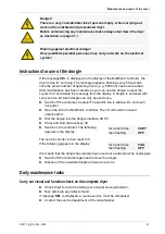
Slowly open compressed air outlet valve! 

Avoid a sudden drop in pressure in any circumstance! If pressure drops 
too fast, this may cause damage to the dryer. Therefore, the compressed air 
outlet valve must always be opened quite slowly! 


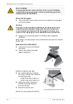
  Slowly open the compressed air outlet valve installed by the owner. The 

pressure should not drop below the operating pressure (if poss.). If 
necessary, keep the compressed air outlet valve in a slightly open position 
until the compressed air system downstream of the dryer has filled up 
completely; only then should the valve be opened fully. 

  If available, block off bypass line. 

The dryer is now in operation again and operates fully automatically.  


If compressed air system and dryer have not remained at operating pressure 

  If disconnected, reconnect the voltage supply of the dryer. 

  Ensure that the manual drain on the downstream filter is closed.  

  Pressurise and switch on the dryer as described in the section 

Open 

compressed air supply and switch on dryer

 on page 31. 

The dryer is now in operation again and operates fully automatically. 


Содержание K-MT 1-8

Страница 1: ...Adsorption dryer ecodry K MT 1 8 Operating instructions Revision 08 2014 EN...

Страница 2: ...EC and were subjected to a conformity assessment according to Annex III Module A The assembly consists of pressure appliances according to the classification list attached to the technical documentati...

Страница 3: ...ressure equipment 97 23 EC but must not bear the CE mark due to Art 3 Para 3 97 23 EG The quality control system is monitored by Lloyd s Register Quality Assurance GmbH Hamburg code no 0525 The follow...

Страница 4: ...ve to keep these appliance data up to date The above stated appliance data provide for a clear identification of the dryer and its components and significantly facilitate any service measures Further...

Страница 5: ...on packaging 19 What to do in the case of transport damage occurring 19 Transporting and installing the dryer 20 Storing the dryer 22 Installation 23 Preconditions for installation 23 Connect piping 2...

Страница 6: ...nance work to be completed every 12 months 42 Maintenance work to be completed every 24 months 44 Maintenance work to be completed every 48 months 45 Identify and eliminate faults 50 Summary of faults...

Страница 7: ...ler Control system Associated documents Operating instructions present Technical documentation see annex Circuit diagrams see separate document Operating manual for installed filters separate document...

Страница 8: ...uch damage Danger These danger notes with a grey background warn against personal injury and or danger to life and limb danger notes help you to avoid serious or life threatening situations for yourse...

Страница 9: ...personnel not used within its intended design specifications is repaired or maintained incorrectly Note For your own safety and to prevent machine damage please note the information and safety notes...

Страница 10: ...carry electrical current These parts may be connected opened and maintained by authorized specialist personnel only Warning against overpressure The entire dryer is under pressure Before commencing an...

Страница 11: ...ads They could fracture tear off or become damaged in another way General safety notes For your own safety when carrying out any work on the dryer comply with all applicable national safety regulation...

Страница 12: ...en escape of pressure may cause serious injuries Before carrying out any work on the dryer first depressurise the plant Carry out all prescribed tests and checks The factory settings on the control bo...

Страница 13: ...supply line and set the ON OFF switch of the dryer to 0 in order to disconnect it from the power supply Afterwards depressurise the dryer see also chapter page 37 The unit may only be restarted after...

Страница 14: ...n release of pressure Never remove any parts of the dryer or manipulate the same in any way for as long as the plant is still pressurised A sudden escape of pressure may cause serious injuries Before...

Страница 15: ...he dryer dries the compressed air supplied by the compressor and makes it available for industrial use Upstream filters clean the compressed air and remove dust dirt oil and water droplets before the...

Страница 16: ...the adsorption At the same time the other chamber is prepared for a renewed take up of humidity This process is called regeneration The regeneration is subdivided into three phases expansion dehumidi...

Страница 17: ...the vessels will be effected between the vessels Following switchover the above described process is repeated with the adsorption and regeneration now taking place in the respective different vessel A...

Страница 18: ...ain compressed air volume is reached behind the dryer The regeneration process must be continued and ended so that the drying agent does not become unusable prematurely Dewpoint sensing control With a...

Страница 19: ...pe of transportation the dryer is delivered in different types of packaging All transportation types the apertures of the dryer are closed off by means of plugs In addition when transportation is effe...

Страница 20: ...ation proof It must have the necessary carrying capacity for the weight of the dryer The weight of the dryer is specified in the technical data section of the annex The dryer should be installed with...

Страница 21: ...e floor The upright stand profiles of the dryer are provided with pre drilled anchorage bores see figure Use suitable attachment material to anchor the dryer to the floor In the case of vibrating floo...

Страница 22: ...nd the installed compressed air outlet valve installed by the owner are both closed and that the dryer is depressurised Disconnect dryer from the compressed air system Disconnect the dryer from the el...

Страница 23: ...installed and maintained in a depressurised condition see also the installation example on page 24 All pipes couplings and connections must have the correct diameter and match the operating pressure H...

Страница 24: ...ct the dryer to the compressed air system The following figure shows an installation example Compressed air system Item Component 1 Entry humid air 2 Compressed air inlet valve owner end 3 Upstream fi...

Страница 25: ...customer Make the electrical supply cable to the dryer voltage free Secure the electrical supply cable to the dryer against switch on Undo bolt 1 on the connector and withdraw connector with seal from...

Страница 26: ...inals 1 and 2 on the control board see circuit diagram Hinweis The compressor synchronisation controller is a higher level controller than the pressure dew point controller When both options are in pl...

Страница 27: ...ns All shutdown valves of the compressed air inlet and outlet valves installed by the owner in the bypass line if available are closed The dryer is correctly sited and installed Checks before start up...

Страница 28: ...55 min maximum Overview of operating and control elements ON OFF switch The ON OFF switch 2 is located to the side of the switchbox and above the mains plug 1 see figure If it is set to 0 the power s...

Страница 29: ...the dryer are indicated by means of 4 LEDs Vessel B1 Vessel B2 Regeneration 1 Regeneration 2 Adsorption 1 Adsorption 2 Depending on the operating phase the following LEDs might be on simultaneously Ad...

Страница 30: ...t value is flashing With the optional dewpoint sensing control the following error messages might be displayed Display Cause 20 Upper measuring range limit exceeded 999 Dewpoint sensor defective sens...

Страница 31: ...l requirements in your country it may be necessary to perform initialisation according to the directive for pressure equipment 97 23 EC Check the dryer regularly for externally visible damage and defe...

Страница 32: ...ith our recommendation proceed as follows Ensure that the compressed air outlet valve installed by the owner is closed Keep the compressed air outlet valve closed for the time period recommended above...

Страница 33: ...d up phase and prior to switchover during this phase the pressure in both chambers is just below operating pressure so that a fast pressure build up is prevented when the chambers are switched During...

Страница 34: ...rol operated in variable cycle mode based on the measured dewpoint of the dried air at the compressed air outlet As soon as a certain dewpoint is reached as the drying agent in the absorbing chamber i...

Страница 35: ...x shows the currently measured dewpoint The range of display is 100 C 148 F to 20 C 68 F If the set dewpoint is exceeded the system automatically completes a switchover between the chambers The dewpoi...

Страница 36: ...rating chamber is released to ambient pressure If the main valve is opened as the dryer is switched off there is a sudden pressure build up in the chamber This might result in damage to the drying age...

Страница 37: ...he dryer by setting the ON OFF switch to position 0 Disconnect dryer from compressed air system Close the compressed air outlet valve installed by the owner If available open bypass line Depressurise...

Страница 38: ...it was interrupted Slowly open compressed air outlet valve Avoid a sudden drop in pressure in any circumstance If pressure drops too fast this may cause damage to the dryer Therefore the compressed a...

Страница 39: ...ut down and depressurised Bolt connections must be undone with care Note ram pressure values Otherwise emerging media may cause personal injury Do not modify the factory settings of the control system...

Страница 40: ...12 months 24 months 48 months see page Complete dryer Carry out visual and function checks 41 Muffler K MT 1 2 Clean muffler replace if necessary 42 K MT 3 8 Mufflers must be replaced annually and af...

Страница 41: ...every service kit Each dongle can only be used once Switch off the controller Caution The electric line is still live Do not touch live parts Open the lid to the Multitronic controller The circuit boa...

Страница 42: ...ore mufflers must be checked at least once a year and cleaned K MT 1 2 or renewed K MT 3 8 if they are contaminated Warning against sudden air ejection During expansion the pressure is released sudden...

Страница 43: ...point measurement it is recommended to replace the dew point sensor every year This period depends however on the actual application and might thus be extended accordingly Dewpoint sensor 1 Warning T...

Страница 44: ...lace seal onto sealing face connect adapter 1 and secure it by tightening the screw If no other maintenance work is to be carried out Restart the dryer see page 38 Place the protective caps 4 5 onto t...

Страница 45: ...dryer and shut down the unit see page 37 Remove the securing screws at the rear of the check valve plate Insert new balls and new springs and ensure that they are not jammed Replace the seals at the...

Страница 46: ...ter stage Solenoid valve For each solenoid valve proceed as follows Remove solenoid valve from the holder 3 Remove the valve together with the solenoid and the diaphragm 4 Insert new diaphragm with gu...

Страница 47: ...However in favourable installation conditions the change of drying agent may be carried out at a substantially later date for notes on the installation site see also page 20 The change interval is de...

Страница 48: ...e code numbers of the drying agent can be obtained from the manufacturer Dispose of the used drying agent in accordance with all applicable regulations Before filling in new drying agent we recommend...

Страница 49: ...achieve an optimum bulk density we recommend using a snowstorm filling pipe available from the manufacturer Subsequently position the perforated plate onto the check valve plate align them properly an...

Страница 50: ...d to remedy a fault the owner s specialist personnel or the manufacturer s service engineer Table of possible faults Fault Possible cause Remedy Specialised personnel Service technician No pressure bu...

Страница 51: ...ensing control optional Fault code Description of fault Possible cause Remedy Specialised personnel Service technician 20 Upper measuring range limit exceeded Drying capacity exceeded See instructions...

Страница 52: ...re 4 Dehumidification explanation 16 Demister maintenance 48 Dewpoint sensing control 18 Differential pressure gauge 15 Digital display explanation 29 Documentation technical 54 Dongle use 41 Dryer ma...

Страница 53: ...explanation 17 sudden 31 Pressure Conditions 38 Pressure vessel 39 Programme sequence steps 57 Protection class 55 R Regeneration explanation 16 Regulations for accident prevention 19 20 Replacement...

Страница 54: ...2014 Annex with technical documentation This annex comprises the following information and technical documentation Technical data Replacement and wear parts list Logic control diagram Flow diagram Dim...

Страница 55: ...lter Downstream filter Nominal Pressure in bare Nominal temperature C K MT 1 8 1 4 GL2XL GL2ZLH 16 50 K MT 2 15 1 4 GL2XL GL2ZLH 16 50 K MT 3 25 1 4 GL2XL GL2ZLH 16 50 K MT 4 35 1 4 GL2XL GL2ZLH 16 50...

Страница 56: ...115V SKK1 K4 D2 48 115 K MT 6 to K MT 7 12 and 36 months 115V 230V SKK6 K7 D2 12 Reset module muffler and filter elements K MT 6 to K MT 7 24 months 115V 230V SKK6 K7 D2 24 Reset module valve membran...

Страница 57: ...Annex with technical documentation K MT1 8_EN_08 2014 57 Logic control diagram Adsorption in B1 and regeneration in B2...

Страница 58: ...Logic control diagram 58 K MT1 8_EN_08 2014 Regeneration in B1 and adsorption in B2...

Страница 59: ...Control system 10 102 Perforated plate 80 Upstream filter 10 107 Demister left 90 Downstream filter 10 108 Demister right 100 Muffler 10 109 Left perforated plate Optional devices 10 110 Conical press...

Страница 60: ...Dimensional drawing 60 K MT1 8_EN_08 2014 Dimensional drawing Installation on floor...

Страница 61: ...101 90 91 11 5 K MT 2 1 4 326 575 540 216 217 551 517 101 101 90 91 15 5 K MT 3 1 4 326 825 790 216 217 801 767 101 101 90 91 20 0 K MT 4 1 4 326 1075 1040 216 217 1051 1017 101 101 90 91 25 0 K MT 6...

Отзывы: