4. CiA 402 Drive Profile
35
4.1
Drive Status Control
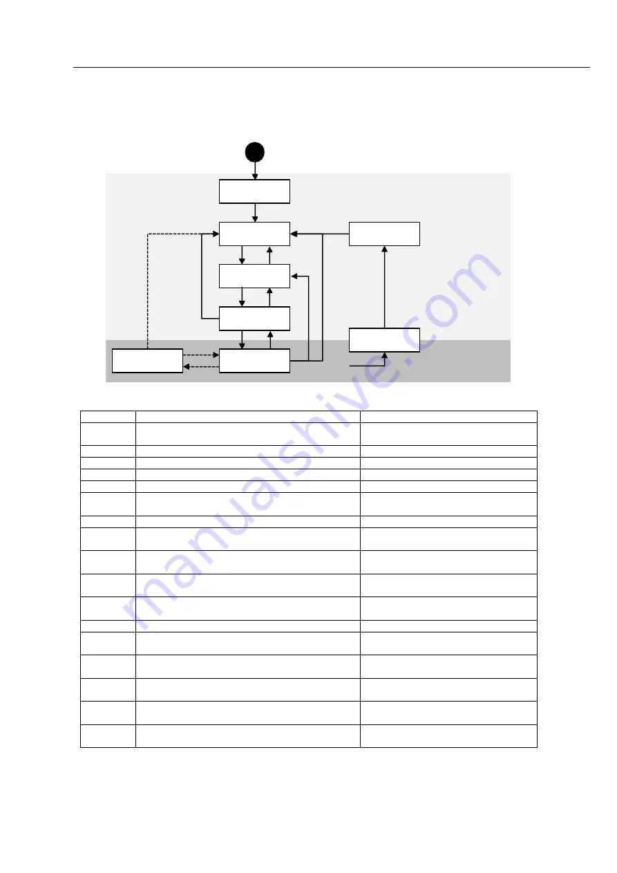
Status of product moves as follows. Status movement is executed by status of controller and Control word
(6040h) and current status can be checked by Status word (6041h).
Figure 4.1: Power Drive System State Machine
Status movement and meaning of each status is as follows.
Table 4.1: State transition
Start
0
Low level power
Supply Controller Power
1
15
2
7
12
10
3
14
6
8
9
4
16
5
Torque
Supply Motor Power
11
13
Error Detected
Not ready to
switch on
Switch on
disabled
Fault
Ready to
switch on
Switched on
Fault reaction
active
Quick stop
active
Operation
Enabled
Transition Event
Action
0
Automatic transition after power-on or reset appli-
cation
Drive self-test and/or self initialisation
shall be performed.
1
Automatic transition
Communication shall be activated
2
Shutdown command from control device
3
Switch On command from control device
4
Enable Operation command from control device
The drive function shall be enabled.
5
Disable Operation command from control device
The drive function shall be disabled,
Motor power shall be switched off.
6
Shutdown command from control device
7
Quick Stop or Disable Voltage command from con-
trol device
8
Shutdown command from control device
The drive function shall be disabled,
Motor power shall be switched off.
9
Disable Voltage command from control device
The drive function shall be disabled,
Motor power shall be switched off.
10
Quick Stop or Disable Voltage command from con-
trol device
11
Quick Stop command from control device
The quick stop function shall be started.
12
Automatic transition (depends on the Quick stop
option code)
The drive function shall be disabled,
Motor power shall be switched off.
13
Fault signal
the configured fault reaction function
shall be executed.
14
Automatic transition
The drive function shall be disabled,
Motor power shall be switched off.
15
Fault Reset command from control device
A reset of the fault condition is carried
out.
16
Enable Operation command from control device
(depends on the Quick stop option code)
The drive function shall be enabled.
Содержание ECL E Series
Страница 6: ...Introduction Before Operation 6 ...
Страница 8: ...Chapter 1 Product Specification 10 ...
Страница 9: ...11 1 1 Part Numbering ...
Страница 10: ......
Страница 11: ...13 1 2 Product Dimension Figure 1 3 Dimensions ...
Страница 14: ...Chapter 2 Installation 16 ...
Страница 16: ...2 2 System Configuration EtherCAT Cable Figure 2 1 System Configuration Diagram ...
Страница 17: ...2 3 External Wiring Diagram ...
Страница 18: ......
Страница 24: ... Less than 30V of supplyvoltage Less than 15mA of current flow ...
Страница 26: ...Chapter 3 EtherCAT Communication ...
Страница 27: ... 26 ...
Страница 28: ......
Страница 36: ...Chapter 4 CiA 402 Drive Profile ...
Страница 37: ... 34 ...
Страница 38: ......
Страница 46: ...9 15 Reserved Table 4 12 Profile Position Mode of Control Word Please refer to 4 3 for the rest of bits ...
Страница 52: ...Please refer to drive status control for the rest of bits ...
Страница 66: ...Chapter 5 Operataion ...
Страница 67: ... 59 ...
Страница 72: ...Chapter 6 EtherCAT Object Dictionary ...
Страница 73: ... 63 ...
Страница 82: ......
Страница 89: ...6 EtherCAT Object Dictionary 77 6061h 0 Mode of operation display I8 RO No Tx PDO ...
Страница 107: ...6 EtherCAT Object Dictionary ...


