5.1
Operation Sequence
Sequence of controller operation is as follow. Exampled operation sequence of Profile Position Mode listed at
the table as below..
Step
Name
Action
1
Setting
Installation
Install motor/controller according to conditions of installa-
tion.
2
Wiring
Check power cable, motor/encoder cable, I/O cable, Ether-
CAT communication cables are properly connected.
3
Input power
Turn power on. Check controller status.
4
PDO Mapping
Set Module/PDO Mapping.
5
Set communication status
Change EtherCAT State Machine as ‘OP’
6
Operation
Control Drive Status
Set Control Word then change Drive State Machine to Op-
eration Enabled.
7
Set Mode
Set Object 6060h: Mode of operation.
8
Set Operation
Input value into Object needed for execution of Motion.
9
Movement Command
Execute command by setting of Control word.
10
Check Status
Check the status of Motion execution.
11
Set Drive
Reset object if need.
5.2
Setting
5.2.1
Installation
Install motor/controller according to conditions of installation. Check operation in advance under unload status
and recommend to connect Load. Please refer to
2.1 Precautions of Installation
5.2.2
Wiring
Check power cable, motor/encoder cable, I/O cable, EtherCAT communication cables are properly con- nected.
Please refer to
5.2.3
Input Power
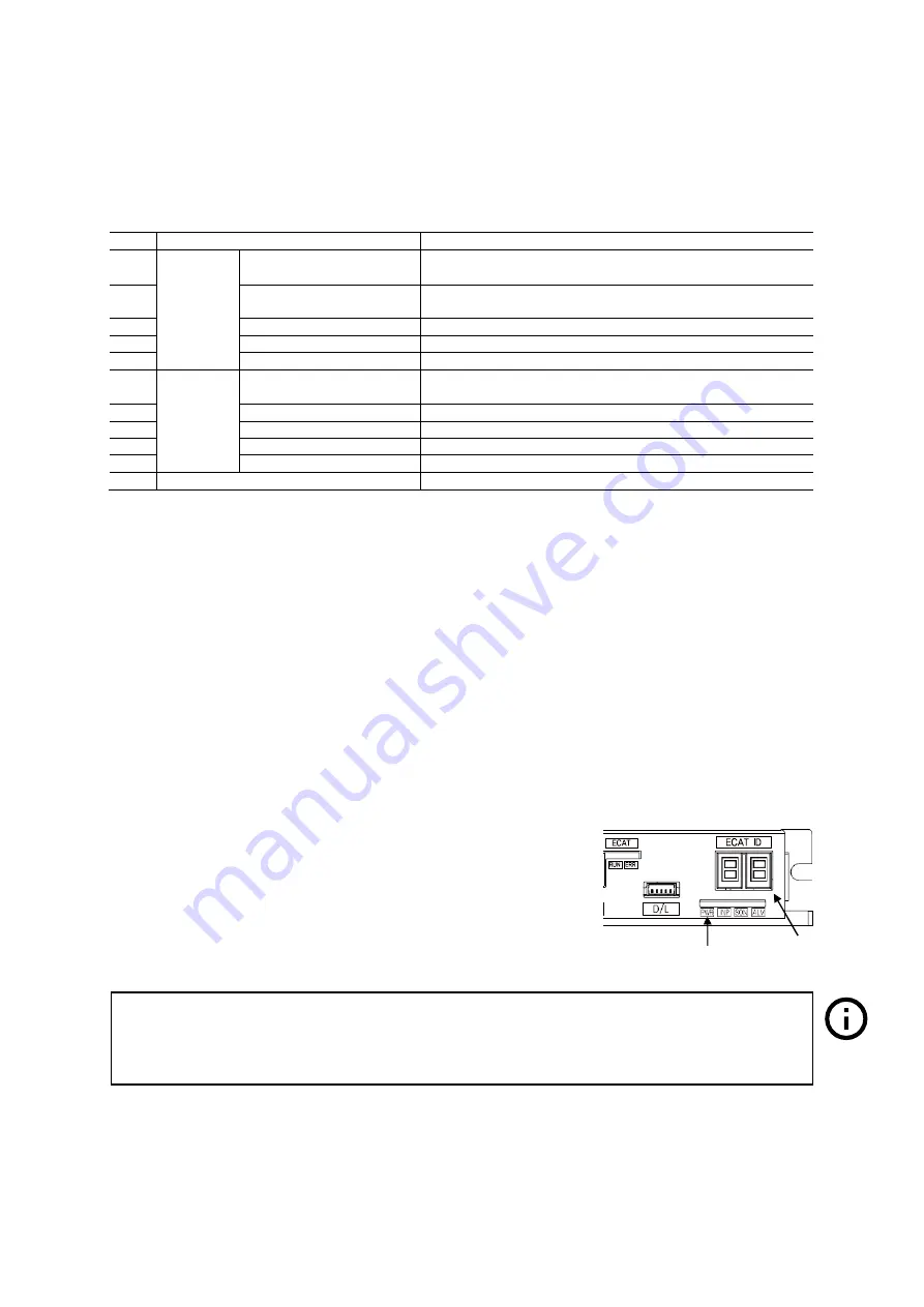
Turn power (24V DC) onto controller and check followings.
•
Check Power LED (Red Color) of Drive status LED lights.
•
Check 7-Segment indicates 0 or other value.
5.2.4
PDO Mapping
Set Module and PDO Mapping by setting function of Master.
5.2.5
Set Communication Status
Change EtherCAT State Machine as ‘OP’ status by controlling Master.
•
Check State Machine of Master can be changing to ‘OP’ status.
•
Check State Machine of Controller can be changing to ‘OP’ status.
Information
Trial operation explains operation by Profile Position Mode.
Select the Module: ‘Axis (Normal) : dynamic select operation mode’.
Name of Module can be differentiated by each Master.
Содержание ECL E Series
Страница 6: ...Introduction Before Operation 6 ...
Страница 8: ...Chapter 1 Product Specification 10 ...
Страница 9: ...11 1 1 Part Numbering ...
Страница 10: ......
Страница 11: ...13 1 2 Product Dimension Figure 1 3 Dimensions ...
Страница 14: ...Chapter 2 Installation 16 ...
Страница 16: ...2 2 System Configuration EtherCAT Cable Figure 2 1 System Configuration Diagram ...
Страница 17: ...2 3 External Wiring Diagram ...
Страница 18: ......
Страница 24: ... Less than 30V of supplyvoltage Less than 15mA of current flow ...
Страница 26: ...Chapter 3 EtherCAT Communication ...
Страница 27: ... 26 ...
Страница 28: ......
Страница 36: ...Chapter 4 CiA 402 Drive Profile ...
Страница 37: ... 34 ...
Страница 38: ......
Страница 46: ...9 15 Reserved Table 4 12 Profile Position Mode of Control Word Please refer to 4 3 for the rest of bits ...
Страница 52: ...Please refer to drive status control for the rest of bits ...
Страница 66: ...Chapter 5 Operataion ...
Страница 67: ... 59 ...
Страница 72: ...Chapter 6 EtherCAT Object Dictionary ...
Страница 73: ... 63 ...
Страница 82: ......
Страница 89: ...6 EtherCAT Object Dictionary 77 6061h 0 Mode of operation display I8 RO No Tx PDO ...
Страница 107: ...6 EtherCAT Object Dictionary ...


