9
For assistance, call toll-free at 800-343-4048
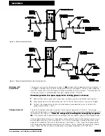
After all the components have been properly installed (see Figure 5), the following procedure should
be followed to ensure optimal operation of the entire nitrogen supply system.
1
1
1
1
1
Set the inlet pressure to the Balston Nitrogen Generator using the customer-provided pressure
regulator, and initiate the air flow through the system.
2
2
2
2
2
Set the flow control valve to its fully open position. The nitrogen flow meter reading should be at
the top of the scale.
3
3
3
3
3
Close the shut-off valve to the process and open the vent valve downstream from the receiving
tank to prevent substandard nitrogen from entering the process.
4
4
4
4
4
Fully open the outlet pressure regulator on the nitrogen generator, and adjust the back pressure
controller until the outlet pressure gauge on the nitrogen generator reads 10 psig (0.7 bar) less
than the desired nitrogen storage pressure. Maximize the storage pressure to minimize the size
of the receiving tank needed.
5
5
5
5
5
Set the flow control valve on the front panel of the nitrogen generator to the proper reading, as
specified by the Nitrogen Purity Label. Read from the middle of the ball.
6
6
6
6
6
Purge the entire system for 5 minutes, venting the initial nitrogen stream through the vent valve
to atmosphere.
7
7
7
7
7
Close the vent valve, open the process shut-off valve, and initiate the flow of nitrogen to the
process.
The use of a receiving tank upstream from the process, as detailed in this literature, significantly
reduces the effects of fluctuating nitrogen demand on the purity of the emergent nitrogen process
stream from the Balston Nitrogen Generator. Parker recommends a 5 minute purge of the system
(see Step 3 above) each time the unit is started.
If the temperature of the inlet air to the Balston Nitrogen Generator differs from the temperature of
the module (i.e. ambient temperature), the system must be allowed to reach temperature equilibrium
before a constant purity of nitrogen is delivered from the system. If the temperature difference is
10°F-20°F (5°C-11°C), this equilibrium period may be as long as 60 minutes. The inlet air tempera-
ture and, more importantly, inlet air dewpoint, must not be higher than the temperature of the system
or condensation of water within the system may occur, resulting in inefficient performance of the
system and/or damage to the membrane.
Performance of the Balston Nitrogen Generator is highly dependent on the temperature of the inlet
air. The data on purity and flow rate presented in this bulletin is based on an inlet air temperature of
68°F (20°C). If the temperature of the inlet air at the point of use for this system varies from 68°F
(20°C) by more than 5°F (3°C), the factory must be consulted for flow and purity information.
The optimum performance of the Balston Nitrogen Generator is dependent on system parameters
remaining stable and accurate; therefore, the system should be checked at least once per week.
This routine system check should include correcting any changes in the flowmeter reading, confirm-
ing pressure gauge reading stability and operating pressure setting, checking the downstream
flowmeter (if applicable) to ensure flows are consistent with the required nitrogen purity level, and
calibrating the oxygen analyzer.
System upsets relative to pressure or flow rate will result in variations in purity of the outlet gas.
System upsets relative to temperature, dewpoint, or hydrocarbon content of the inlet compressed air
may result in variations of the system performance. These types of upsets should be eliminated
from the compressed air delivery system to assure consistent performance of the Balston Nitrogen
Generator.
Proper shutdown of the Balston Nitrogen Generator can be accomplished by simply closing the inlet
air gate valve and turning off the oxygen analyzer. If the inlet valve is left open, the system will
continue to consume inlet compressed air. Closing the outlet flow control valve will not prevent air
consumption because the membrane module permeate ports are open to atmosphere.
Operation/Calibration
Receiver Tank
Applications
Operation: Adjustment Procedure
Temperature Equilibrium
Evaluation
System Upsets
Shutting Down


