3
For assistance, call toll-free at 800-343-4048
Description
Oxygen Monitoring
Controls
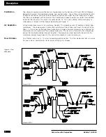
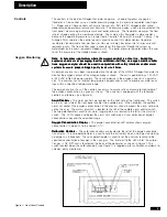
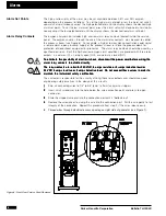
The controls in the Balston Nitrogen Generator comprise: an operating pressure gage, a
flowmeter, a flow control valve, an outlet pressure gauge, and a pressure regulator (see Figure
1). Proper use of these controls will assure the user of a 95% to 99% nitrogen outlet stream,
depending on operating pressure and flow rate. The pressure gages, which are mounted on the
front panel, measure operating pressure and outlet pressure. The flowmeter measures the flow
rate of nitrogen exiting the membrane module. The scale on this flowmeter is dimensionless
because the operating pressure can range from 60 psig to 145 psig (4.1 barg to 10 barg). The
Nitrogen Purity Label on the control panel is used to convert this dimensionless flowmeter
reading to standard cubic feet per hour (or liters per minute), based on inlet air pressure and
required purity. The flow control valve is used to set the flow rate through the system as
determined by the user’s required nitrogen purity. The outlet pressure regulator allows the user
to set the pressure of the nitrogen process stream.
Note: In hazardous applications where the oxygen content is critical (i.e., blanketing
Note: In hazardous applications where the oxygen content is critical (i.e., blanketing
Note: In hazardous applications where the oxygen content is critical (i.e., blanketing
Note: In hazardous applications where the oxygen content is critical (i.e., blanketing
Note: In hazardous applications where the oxygen content is critical (i.e., blanketing
explosive chemicals or packaging food for extended shelf life), an oxygen monitor and/or
explosive chemicals or packaging food for extended shelf life), an oxygen monitor and/or
explosive chemicals or packaging food for extended shelf life), an oxygen monitor and/or
explosive chemicals or packaging food for extended shelf life), an oxygen monitor and/or
explosive chemicals or packaging food for extended shelf life), an oxygen monitor and/or
trace oxygen analyzer should be used in conjunction with safety interlocks and/or alarm
trace oxygen analyzer should be used in conjunction with safety interlocks and/or alarm
trace oxygen analyzer should be used in conjunction with safety interlocks and/or alarm
trace oxygen analyzer should be used in conjunction with safety interlocks and/or alarm
trace oxygen analyzer should be used in conjunction with safety interlocks and/or alarm
systems to assure proper nitrogen purity levels at all times.
systems to assure proper nitrogen purity levels at all times.
systems to assure proper nitrogen purity levels at all times.
systems to assure proper nitrogen purity levels at all times.
systems to assure proper nitrogen purity levels at all times.
An oxygen analyzer has been incorporated into the design of the HFX0-3 Nitrogen Generator to
monitor the oxygen content of the nitrogen process stream. The unit is powered by a 120 VAC
or 240 VAC, 50/60 Hz power supply. The sensing device in the oxygen analyzer is a galvanic
cell. The analyzer has an internal temperature compensation circuit to provide accurate read-
ings within a specified temperature range.
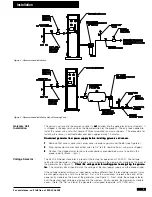
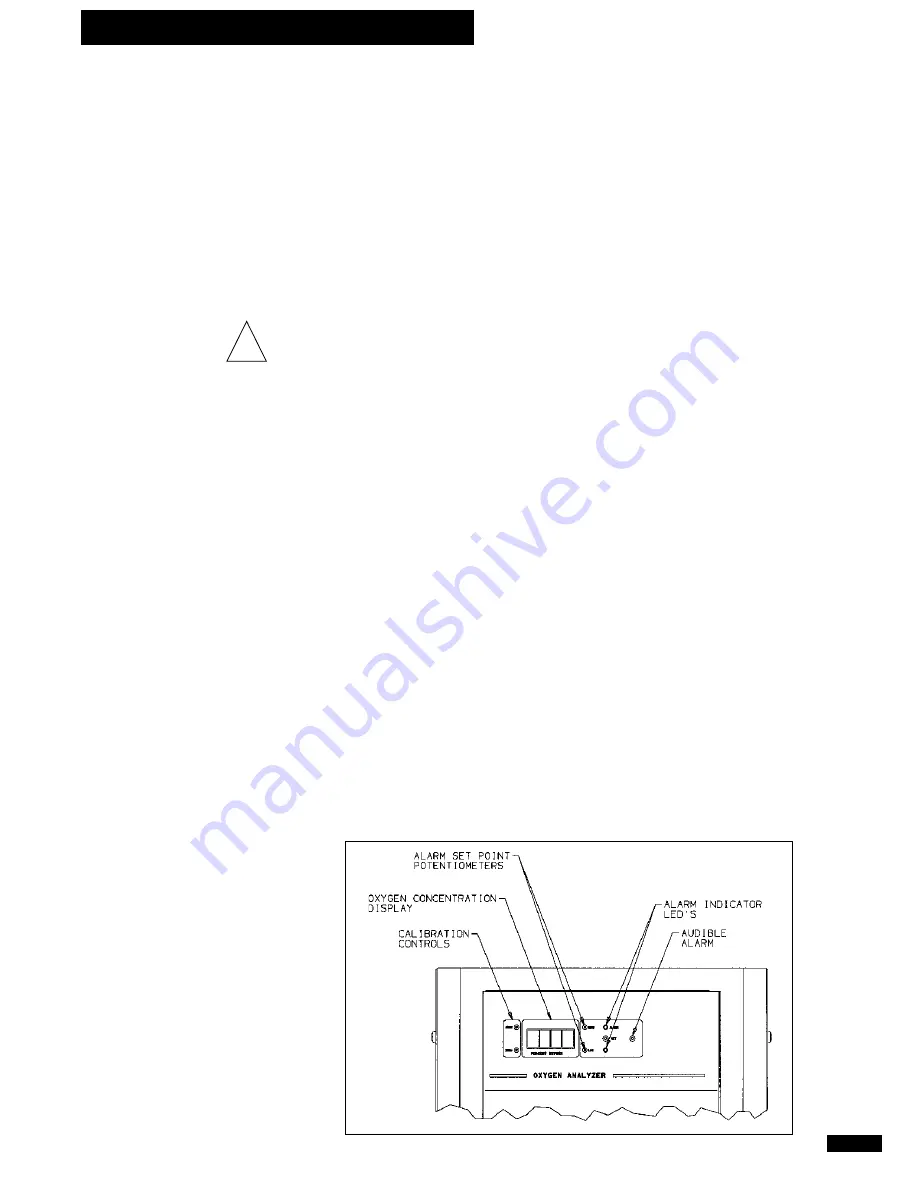
The oxygen analyzer has all the controls necessary to assure safe and accurate monitoring of
the oxygen concentration in a process stream. The analyzer is equipped with the following
controls and features (see Figure 3):
Alarm Controls -
Alarm Controls -
Alarm Controls -
Alarm Controls -
Alarm Controls - The alarm controls are located on the right side of the front panel. The switch
on the far right side of the front panel enables the audible alarm. When enabled, the audible
alarm will sound if the oxygen concentration in the process stream exceeds the alarm set points
set by the user. The alarm set switch is located to the left of the audible alarm control switch.
The two potentiometers used to set alarm trigger points are located to the left of the alarm set
switch. The LED’s above and below the alarm set switch give a visual indication of oxygen
concentrations beyond the specified range.
Oxygen Concentration Display -
Oxygen Concentration Display -
Oxygen Concentration Display -
Oxygen Concentration Display -
Oxygen Concentration Display - The oxygen concentration LED display shows oxygen
concentration, in percent, to the nearest 0.1%.
Calibration Controls -
Calibration Controls -
Calibration Controls -
Calibration Controls -
Calibration Controls - The calibration controls are located to the left of the oxygen concentra-
tion display. The zero potentiometer is used to zero the instrument when a zero gas (containing
no oxygen) is introduced. The span potentiometer is used to set the analyzer reading to the
specified concentration of oxygen in the span gas. The inlet port to the HFX0-3 for the calibra-
tion gas is 1/8" NPT and is located on the back of the generator, as shown in Figure 1. The
switch located below the calibration port (see Figure 1) is toggled up for calibration and down for
nitrogen purity monitoring.
Figure 3 - Front Panel Controls
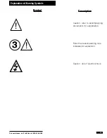
!


