6
Parker Hannifin Corporation
Bulletin TI-HFX-3D
Alarms
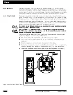
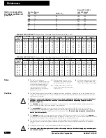
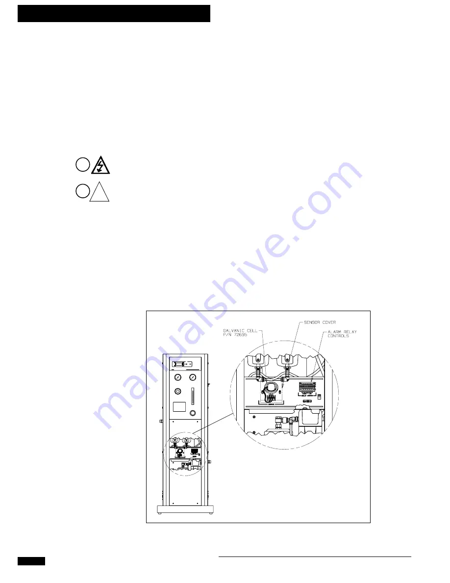
Figure 6 - Front View, Service Panel Removed
!
Alarm Set Points
4
1
Alarm Relay Contacts
The high and low limits of the alarm may be set anywhere between 0.5% and 25% oxygen,
depending on the process limitations. To set the high alarm set point, press the alarm set switch
upward and simultaneously adjust the high potentiometer until the display shows the desired high
alarm set point. To set the low alarm set point, press the alarm set switch downward and simulta-
neously adjust the low potentiometer until the display shows the desired low alarm set point.
The oxygen analyzer also includes high and low alarm relay contacts located inside the service
panel. The oxygen analyzer, through the use of the alarm relay contacts, may be used to control
the process stream (see Figure 6). For example, a high or low oxygen concentration could signal
a remote alarm, open a backup supply of the process stream, or close the process down for
protection of downstream equipment or processes. The alarm relay contacts should be wired by a
qualified electrician. Both the high and low oxygen alarm conditions are provided with three relay
outputs: a common (C), a normally open (NO), and normally closed (NC).
To eliminate the possibility of electrical shock, disconnect the power cord before wiring the
To eliminate the possibility of electrical shock, disconnect the power cord before wiring the
To eliminate the possibility of electrical shock, disconnect the power cord before wiring the
To eliminate the possibility of electrical shock, disconnect the power cord before wiring the
To eliminate the possibility of electrical shock, disconnect the power cord before wiring the
alarm relay contacts to outside circuitry.
alarm relay contacts to outside circuitry.
alarm relay contacts to outside circuitry.
alarm relay contacts to outside circuitry.
alarm relay contacts to outside circuitry.
The relay contacts are rated for 250 VAC, 5 amps resistive or 3 amps inductive load or
The relay contacts are rated for 250 VAC, 5 amps resistive or 3 amps inductive load or
The relay contacts are rated for 250 VAC, 5 amps resistive or 3 amps inductive load or
The relay contacts are rated for 250 VAC, 5 amps resistive or 3 amps inductive load or
The relay contacts are rated for 250 VAC, 5 amps resistive or 3 amps inductive load or
24 VDC 5 amps resistive or 3 amps inductive load. Do not exceed these values in order to
24 VDC 5 amps resistive or 3 amps inductive load. Do not exceed these values in order to
24 VDC 5 amps resistive or 3 amps inductive load. Do not exceed these values in order to
24 VDC 5 amps resistive or 3 amps inductive load. Do not exceed these values in order to
24 VDC 5 amps resistive or 3 amps inductive load. Do not exceed these values in order to
maintain the instrument safety certification.
maintain the instrument safety certification.
maintain the instrument safety certification.
maintain the instrument safety certification.
maintain the instrument safety certification.
The customer is responsible for the circuitry utilizing these relay outputs and should use good
engineering safety practices in the design of this circuitry.
1
1
1
1
1
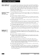
Strip all connecting wires to 1/4" to 3/8" (6mm to 9mm) using wire strippers.
2
2
2
2
2
Insert small screwdriver into the hole below the wire connection point and press to open
connector.
3
3
3
3
3
Slide the stripped wire end into the connection port until it “bottoms out”.
4
4
4
4
4
Remove the screwdriver to clamp the wire into the connection port. Pull the wire gently to test
integrity of the connection. Repeat this procedure from step 2 if the wires release easily.
5
Thread wires through electrical access opening on right side of generator (see Figure 1).


