Refrigerating Specialties Division
7
Clean the sealing surfaces where the Adapter-to-Body Gasket 5 is
to beinstalled and insert a new Gasket in position, making sure to
line up the hole in the Gasket with the passage “N” hole (see Fig.
1) in the Valve Body 1. The gasket should have a very light fi lm of
refrigerant oil applied to both surfaces before inserting in place.
Position the Adapter Cover 22 so the extension of passage N in
the Adapter lines up with the matching hole in the Valve Body 1.
Insert the bolts (and nuts) and tighten to the torques listed in the
table below. These should be tightened in a pattern that provides
a uniform pull-down of the Adapter Cover to the Valve Body.
Inspect the top surface of the Pilot Seat 44 to be sure that
it is smooth and unblemished. This is essential for reliable
performance and for a tight shut-off. If the surface is not good
replace the Pilot Seat with a new part. There is no gasket or O-
ring under the Pilot Seat. Tighten the seat to the torque listed in
the table below
.
Inspect the Diaphragm 45 surfaces to be sure they are clean and
free from scratches, bends or cracks. If range “A” or “V”, there is
only one Diaphragm: if range “D”, there will be two Diaphragms.
Replace any Diaphragms that are defective.
Two Diaphragm Gaskets 43 and 46 are a part of each installation. A
thick, black gasket goes under the Diaphragm 45 against the Valve
Body. and a thin, black gasket goes on top of the Diaphragm. The
Diaphragm(s) is installed bowed toward the Diaphragm Follower
47 and Range Spring 49. That is, the center of the Diaphragm is
higher than its perimeter.
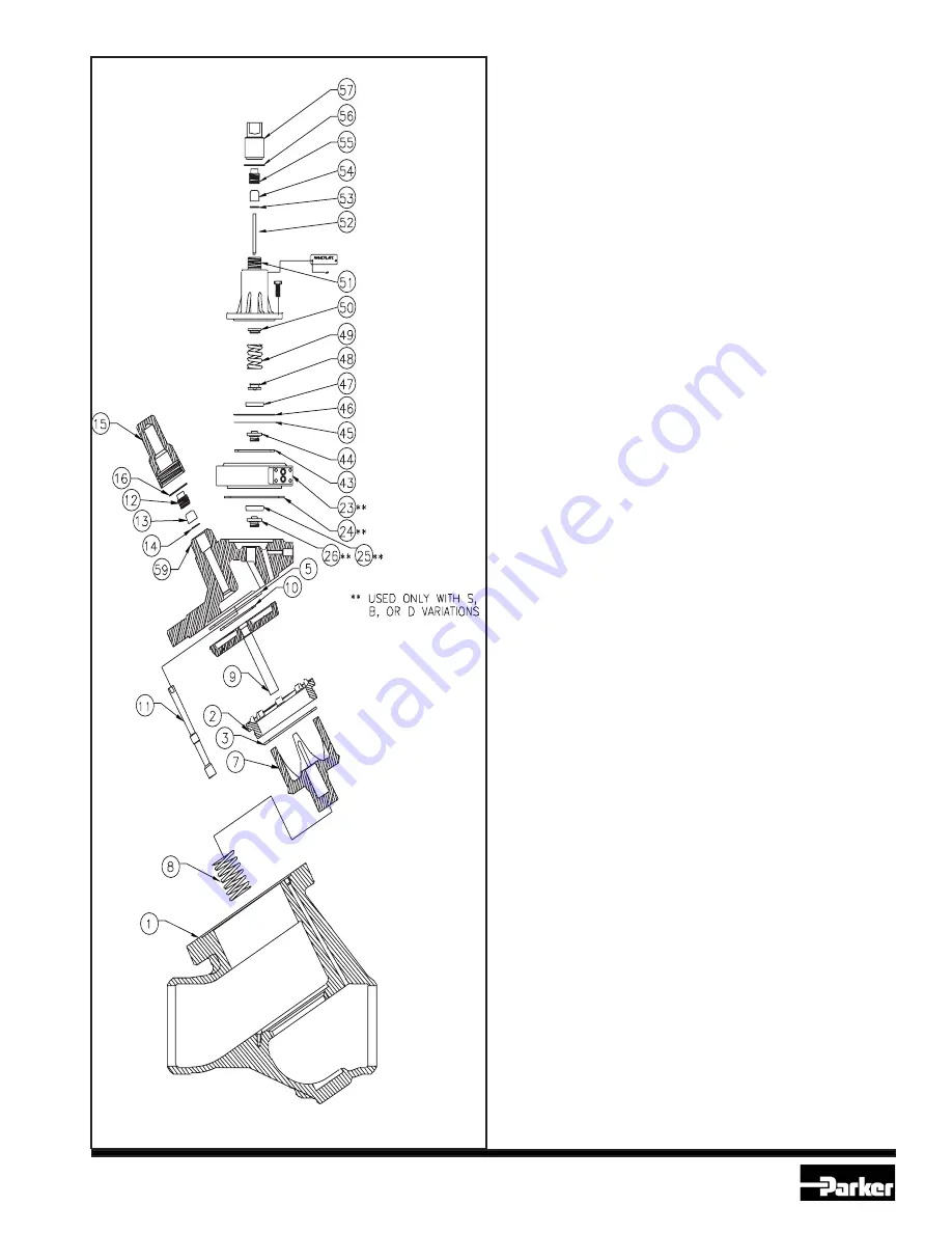
Before installing the Bonnet 51 be sure that the Adjusting Stem
52 is backed out far enough so that when the assembly of Range
Spring 49. Spring Rests 48 and 50, Diaphragm Follower 47 and
Bonnet are put in place, there will be no compression of the
Spring. Place the Diaphragm 45 and both Diaphragm Gaskets 43
and 46 in place on top of the Adapter Cover 22 as described above.
Assemble the Range Spring, Range Spring Rests and Diaphragm
Follower into the Bonnet in the sequence shown in Figs. 1 or
9. This assembly procedure is most convenient if done in the
mechanics hands and not in place on the top of the valve. These
parts can be held in place within the Bonnet as the assembly is
positioned on top of the Adapter at one edge and then slid over to
its proper location. There is no specifi c orientation for the Bonnet.
Insert the Cap Screws 58 and tighten to the torque listed in the
table below. Tighten in a manner that provides a uniform pull-
down of the Bonnet.
Check the assembled valve for leaks to atmosphere. Check the
position of the Manual Opening Stem 11 to be as desired. Set the
Range Adjusting Stem 52 to control the pressure as required.
Tighten Stem Packing Nuts 12 and 55 and install Seal Caps 15
and 57.
TABLE OF TORQUES FOR A4W
FASTENERS AND VALVE SEATS
Metric Units U.S. Units
Item mkg ft/lbs
No. (AlI sizes) (AlI sizes)
Valve Seat (2) 13.8 100
Retaining Screw (4) 2.1 15
Bonnet Cap Screws (58) 1.5 11
Adapter Cover Nuts (18) 14.5 105
Pilot Seat (44) 2.8 20
A2D Body Bolt (60) 0.83 -1.1 6 - 8
S6A Body Bolt (42) 0.83 -1.1 6 - 8
Fig. 7-1


