background image

26

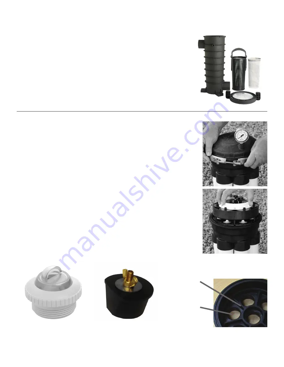
WINTERIZATION PROCEDURE FOR WATER VALVE 

1.  Turn off and drain out all pool equipment.
2.   Remove valve lid or lids from valve(s). Remove module(s) from valve housing(s). Store 

module in dry clean area out of the winter elements for winter until re-installation in 
spring. (See Fig. 1, 2)

3.  Remove any down jet or returns in pool (threaded or slip) including down jet body for a 

secure fit of winterizing plug. Store with module(s). (See Fig. 3)

4.  From valves to pool, place a Schrader plug or blow out plug as recommended. Install 

and secure Schrader or blow out plugs in all parts of valve(s) (except center feed port of 
second and multiple valves when multiple valves are being used). Proceed to blow out 
lines through Schrader or blow out plugs to pool. (See Fig. 4)

5.   While blowing out the in-floor nozzles, once a good amount of air has come through the 

nozzle, you have accomplished an air lock. (This procedure is similar to obtaining an air 
lock when blowing out the bottom drain in the pool.)Blow out center port of first valve 
back to filter equipment and plug.

6.  While blowing out the down jets or any nozzle bodies above freeze zone. and while air is 

escaping through the in-wall hole, install and secure a regular winterizing plug. Repeat 
until all ports are blown out. (See Fig. 4)

7.   In cases where multiple valves are in use, blow out the feeder port of the first valve into 

the center port of the second or multiple valve(s), install, and secure plug. 

8.  When necessary, pool winter anti-freeze solution should be poured into each line.
9.  Valve housing(s) should be wiped clean and dry of water, reinstall top lid and secure. 

WINTERIZATION PROCEDURE FOR  

EQUIPMENT SIDE DEBRIS CANISTER

The EDC canister must be winterized in areas prone to freezing temperatures. 

1.  Remove the EDC canister lid and basket (and optional fine mesh bag). 
2.  Use a wet or dry vacuum to remove all the water from the EDC. 
3.  Replace the EDC lid and proceed with your normal winterizing process. 

Consult your local pool professional for the best winterizing method.

Fig. 1

Fig. 2

Fig. 3

Fig. 4

#9

#6
#11

Содержание ECOSYSTEM

Страница 1: ...4 027 8775 00 REV00 ECN_1752 PUB 042319 295 East Corporate Place Suite 100 Chandler AZ 85225 Toll Free 1 800 621 5886 Phone 480 893 7607 Fax 480 753 3397 Paramount 1Paramount com www 1Paramount com US...

Страница 2: ...ramount com IMPORTANT NOTICE FORWARD PLEASE REVIEW THE OWNER S MANUAL AND INSTALLATION GUIDE IN ITS ENTIRETY AND HEED ALL SAFETY INFORMATION Failure to follow these instructions and warnings can resul...

Страница 3: ...LUMBING DETAIL 10 PLUMBING FLOOR 10 2 NOZZLES ON A LINE 11 3 NOZZLES 11 4 NOZZLES 11 PLUMBING WATER VALVE 12 GLUING INSTRUCTIONS 12 2 VALVE BASE PLUMBING GUIDE 12 VALVE CIRCUIT LAYOUT 13 PLUMBING HEAT...

Страница 4: ...TEM START UP 24 CLEANING NOZZLE INSTALLATION 24 ECO NOZZLE WITH TWIST LOCK CAP 24 INSTALLING NOZZLE IN FLOOR 24 WINTERIZING INSTRUCTIONS 25 WINTERIZATION PROCEDURE FOR IN FLOOR SYSTEM 25 WINTERIZATION...

Страница 5: ...oper chemical balance Brush the pool periodically Clean baskets and filters on a regular basis In conclusion the IN FLOOR SYSTEM is not a 100 cleaner and should never be presented as such SURFACE RETU...

Страница 6: ...ob Name City State Address Contact Name City Zip Sales Person Revisions Telephone Previous Drawing E mail pdf dwg What Is Revised Fax Reply by fax Check Corresponding Boxes And Fill In The Blanks To B...

Страница 7: ...ocation break location overall dimension the nozzle placement must also change A revised plan must be drawn Choose one nozzle to use as a starting point and indicate dimensions to outer walls This wil...

Страница 8: ...the in floor system Additional equipment such as chlorine generators spa overflows water features etc require more water flow Adjust pump GPM requirements accordingly FILTER REQUIREMENTS SELECTING PRO...

Страница 9: ...VENTURI SKIMMER GPM SKIMMER MDX R3 DEBRIS DRAIN SDX MIN FILTER CART 130 D E 48 SAND 49 HEATER CIRCULATION SYSTEM PUMP_____ GPM_____HD OPTIONAL EDC CANISTER OPTIONAL DDC CANISTER PUMP CHLOR RETURN SPA...

Страница 10: ...finished pool floor except for steps and benches Step and bench nozzles should be on a separate port The number of nozzles per port in the floor should be constant whenever possible All pipes should...

Страница 11: ...not plumb nozzles in line all nozzles must be on a branch 3 NOZZLES 4 NOZZLES 2 NOZZLES ON A LINE INCORRECT METHOD OF PLUMBING NOTICE Nozzles will not rotate dependably if plumbing directive is not fo...

Страница 12: ...t in trench 15 deep X 19 wide NOTICE Height of riser pipes may be adjusted as long as the 3 height differential between fittings is maintained GLUING INSTRUCTIONS 1 Remove Clamp 2 Lift off dome save 0...

Страница 13: ...1 PVC PIPE port inlet 2 2 X2 1 4 PVC PIPE port 6 8 2 SLIP 90 elbows Optional replace 2 90 elbows and 2 2 x2 pipes with 2 spigot 90 elbows port 6 Set in trench 19 deep X 12 wide IMPORTANT PORT 1 AND 5...

Страница 14: ...created when all the water is directed through the heater THE IN FLOOR SYSTEM MAY NOT FUNCTION PROPERLY WITHOUT THIS BY PASS NOTE MULTI SPEED PUMPS AND HEATERS HEAT PUMP When plumbed with a bypass the...

Страница 15: ...System EQUIPMENT SIDE DEBRIS CANISTER PLUMBING 8 Minimum Straight Pipe Apply primer twice before gluing pipe or fittings to EDC canister Pump Install 3 Way Valve Ahead of the LeafVac ONLY Suction From...

Страница 16: ...ER MDX R3 SDX2 9 229mm 3 90mm MAIN DRAIN DECKS OVER 4 102mm THICK MAY REQUIRE A LID EXTENSION PLUG CONNECTION 1 50mm EQUALIZER LINE THROUGH POOL WALL TO PUMP 2 75mm LINE TO SECONDARY WALL SUCTION MDX...

Страница 17: ...LUMBING FOR SPA Consult the Paramount MDX R3 VGB Compliant Debris Drain for specific instruction on how to plumb DOWNLOAD INSTRUCTION MANUALS MDX R3 Non Adjustable Concrete www 1paramount com manuals...

Страница 18: ...RE 2 ELBOW PLUMBING FOR SMOOTH BODY PLUMBING NOZZLE BODIES NOTICE All risers must be 90 degrees perpendicular to the finished floor NOTICE All risers must be 90 degrees perpendicular to the finished f...

Страница 19: ...n more than 4 radius on steps or benches 2 Nozzles should be pulled out as far as possible in order to reach corners 3 Reversed radius of step corners will help to eliminate dirty steps This will also...

Страница 20: ...nd create a water stop Verify the angle of the risers as it is imperative that the riser angle be 90 degrees from the finished floor angle Check that the system did not lose pressure prior to shooting...

Страница 21: ...e a cutout or opening approximately 1 deep and 1 bigger than the pipe This cutout will be filled with plaster to create a water stop Remove cap Prime the inside of the pipe NOTICE DO NOT PRIME THE BOD...

Страница 22: ...deep and 1 bigger than the pipe This cutout will be filled with plaster or other finish coat to create a water stop Remove cap Prime the inside of the pipe NOTICE DO NOT PRIME THE BODY SMOOTH BODY INS...

Страница 23: ...alternate blocking off all but one nozzle on that circuit one at a time to clean out any debris Use of the pause control will hold the valve on that port while doing this The equipment needs to run fo...

Страница 24: ...ize from pool plan and using the nozzle tool to twist on caps 4 Turn cap clockwise until it snaps into place Be sure o ring is pushed all the way up to top flange 1 Snap the nozzle onto the install to...

Страница 25: ...ce normal winterization procedures but are instead in addition to them For drain winterization instructions consult manufacturer s instructions for that drain WINTERIZATION PROCEDURE FOR DECK SIDE DEB...

Страница 26: ...ir lock when blowing out the bottom drain in the pool Blow out center port of first valve back to filter equipment and plug 6 While blowing out the down jets or any nozzle bodies above freeze zone and...

Страница 27: ...p is off something is stuck in it Try the following items one at a time until the problem is solved Push the Nozzle down with a pool pole Remove the Nozzle rinse to remove all debris Replace if damage...

Страница 28: ...Turbine turn the Gears If not replace Module All nozzles are floating when the pump is on When all Nozzles are floating or have water running through them all at the same time check the Module Module...

Страница 29: ...ieces 1 4 7 16 1 Each 3 004 527 4120 XX ECO Ribbed Body with Plaster Cap 4 004 527 4762 XX ECO Smooth Body with Plaster Cap Requires the use of a riser 005 252 1520 00 or 005 252 1522 00 5 004 552 545...

Страница 30: ...and Clamp Knob 005 302 0640 00 Band Clamp Nut 005 302 0100 00 Base O Ring Valve Base US 005 302 4002 03 2 Port Base 2 Black 005 302 4012 03 3 Port Base 2 Black 005 302 4018 03 4 Port Base 2 Black 005...

Отзывы: