Page 24
4.7
Ethernet Cables. You must choose your Ethernet cable carefully depending upon
your configuration. If you are connecting your iSCSI Bridge
directly
to a
management computer, a crossover cable is necessary. If you are connecting
through an Ethernet switch or router, a straight-through cable will suffice. The
type of cable used is equally important (see Table 2 below). Note that if you are
connecting the iSCSI Bridge to an Ethernet device that is 1000 Mb/s capable, you
can use either a crossover or straight through wire cable.
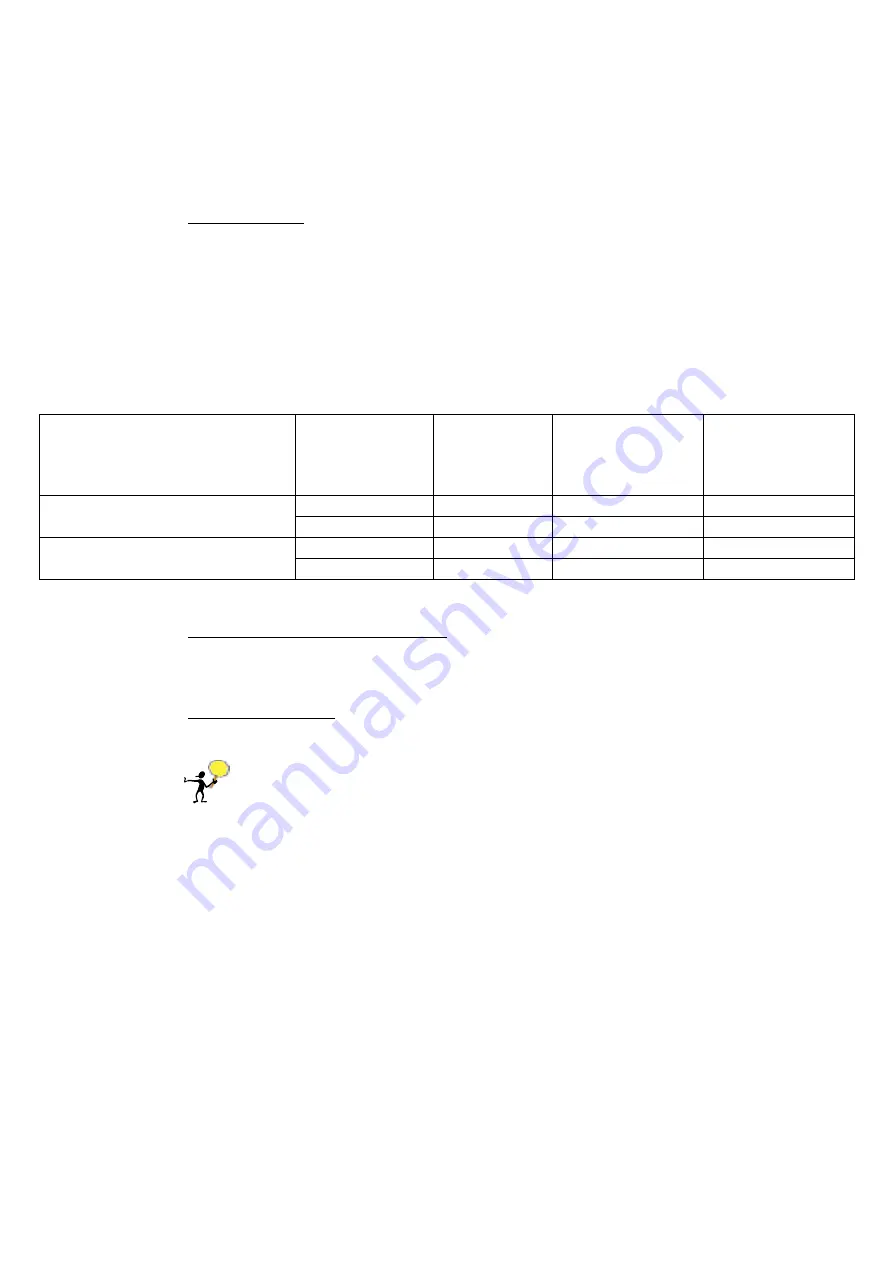
Table 2
Topology
Cable Type
Max
Cable Length
(in meters)
Cable Wiring
Management
Computer/Switch
/Router
Connection Speed
CAT-5 or higher
100m (min)
Crossover
10/100 Mb/s
Bridge
Management Computer
CAT-5E/CAT-6
100m
Straight/Crossover
10/100/1000 Mb/s
CAT-5 or higher
100m (min)
Straight
10/100 Mb/s
Bridge
Switch or Router
CAT-5E/CAT-6
100m
Straight/Crossover
10/100/1000 Mb/s
4.8
Connecting to the Ethernet Network. Simply connect your iSCSI Bridge to your
management computer, switch, router or gateway. For further Ethernet
configuration instruction, refer to section 4.11.
4.9
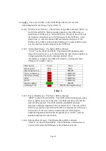
Power On Sequence. Now that you have connected all components of your
iSCSI to SCSI system, it is time to power up the devices.
PLEASE FOLLOW THE POWER UP SEQUENCE BELOW!:
4.9.1
Turn on your SCSI targets and wait for them to be ready.
4.9.2
Apply power to the iS5xx iSCSI Bridge. The iS520 (Stand-Alone Box
Version) unit comes with a power adapter with a lockable connecter to the
iS5xx iSCSI Bridge.
4.9.3
Wait until the Status LED on the bridge turns solid green. The iS5xx
iSCSI Bridge will automatically discover all SCSI targets on the bus. If
there are no SCSI targets connected, the “SCSI” LED will constantly
pulse. In this case, make sure the targets are powered on, the SCSI cables
are connected and the termination is properly placed.
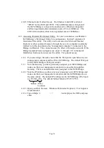
4.9.4
Your SCSI targets are now accessible to your iSCSI network!!!
4.9.5
You may now configure your iSCSI system through its Web-based Utility
using a web browser (see section 4.11).
Содержание iS520
Страница 1: ...Page 1 iS520 iS521 and iS550 User s Manual Version 1 3...
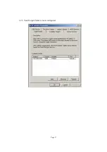
Страница 15: ...Page 15 1 23 Click on the Target Portals tab Add an available portal...
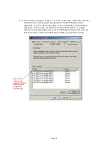
Страница 17: ...Page 17 1 25 Your Target Portal is now configured...
Страница 39: ...Page 39 d iS521 Board version Dimensions are in inches...


