background image

 iii

5100-A2-GB21-00

November 1996

About This Guide

Purpose and Audience

This guide describes how to install and set up the Customer Premises card of the
HotWire 5100 DSL Access System. The guide is written for users of the HotWire
DSL (Digital Subscriber Loop) access system.

Guide Summary

Section

Description

Chapter 1

About HotWire 5100 DSL Access System. Provides a
high-level overview of the operation of the HotWire and lists its
hardware and software requirements for installing the card in
the PC.

Chapter 2

Installation and Setup. Describes how to install and set up the
HotWire card.

Chapter 3

Using the HotWire Diagnostics Utility. Describes how to use
the HotWire Diagnostics Utility.

Appendix A

LEDs. Provides the LED descriptions.

Appendix B

Pin Assignments. Provides the pinouts for the card.

Appendix C

Technical Specifications. Provides the specifications for the
card.

Appendix D

I/O Base Address Switch Settings. Provides a table for switch
settings for possible I/O base addresses.

Glossary

Defines acronyms and terms used in this document.

Index

Lists key terms, acronyms, concepts, and sections in
alphabetical order and provides page references.

Содержание Hotwire 5100

Страница 1: ...HOTWIRE 5100 DSL ACCESS SYSTEM CUSTOMER PREMISES USER S GUIDE Document No 5100 A2 GB21 00 November 1996...

Страница 2: ...rves the right to revise this publication and to make changes from time to time in the contents hereof without obligation of Paradyne Corporation to notify any person of such revision or changes Chang...

Страница 3: ...ory requirements of the country in which it is installed If necessary consult with the appropriate regulatory agencies and inspection authorities to ensure compliance In addition if the equipment is t...

Страница 4: ...ng products Trade Name HOTWIRE Model Numbers 5161 B2 020 5171 B2 020 This device complies with Part 15 of the FCC Rules Operation is subject to the following two conditions 1 this device may not cause...

Страница 5: ...HotWire Diagnostics Utility 1 3 User Interface 1 3 2 Installation and Setup Where to Begin 2 1 Package Contents 2 1 Order of Installation 2 1 Installing the HotWire Diagnostics Utility 2 2 Preparing...

Страница 6: ...ngs 2 16 Checking Card Status 2 17 Troubleshooting Tips 2 18 3 Using the HotWire Diagnostics Utility Accessing the Main Menu 3 1 Checking Hardware Status 3 2 Viewing MAC Address 3 2 Resetting the Card...

Страница 7: ...talling the card in the PC Chapter 2 Installation and Setup Describes how to install and set up the HotWire card Chapter 3 Using the HotWire Diagnostics Utility Describes how to use the HotWire Diagno...

Страница 8: ...About This Guide iv 5100 A2 GB21 00 November 1996 Product Related Documents Document Number Document Title 5100 A2 GB20 HotWire 5100 DSL Access System Central Office User s Guide...

Страница 9: ...r telephone wiring Using the HotWire modem card you can connect to a Central Office CO to access Internet service providers or corporate networks PC with Internal Hotwire Modem PC with Internal Hotwir...

Страница 10: ...s which prevent other users from accessing your PC files or your LAN traffic About the HotWire Card The HotWire card is an ISA 16 bit add on card with a 6 pin telephone modular jack connector used for...

Страница 11: ...h IP stack NDIS 2 01 compliant see note or Windows For Workgroups 3 11 or later or Windows 95 NOTE If the TCP IP software is not installed already you will be asked to install it as a step in the Netw...

Страница 12: ...Diagnostics Utility and Drivers disk Cable HotWire 5100 DSL Access System Customer Premises User s Guide Order of Installation Install and set up your HotWire DSL card by performing the following step...

Страница 13: ...e install program prompts for a destination directory for the Diagnostics Utility you can specify a directory or click on Next to accept the default directory 5 Click on OK when installation completes...

Страница 14: ...ire program icon to access the main menu For a complete description of this menu refer to Chapter 3 3 Select Recommend Base Address from the Configuration menu to display a list of unused base address...

Страница 15: ...system must have a different I O base address 496 14998 1 2 3 4 5 6 7 8 1 2 3 4 5 6 7 8 1 2 3 4 I O Base Address J2 6 Pin Modular Jack Network Access Connector LEDs 6 7 8 ON 1 2 3 4 5 SW1 Procedure To...

Страница 16: ...errupt request is a signal used by your device to inform your CPU when it wants to transfer or receive data Use Switch Banks 2 and 3 SW2 and SW3 to select an IRQ You can use the following illustration...

Страница 17: ...lable IRQ It not refer to your PC documentation for instructions on how to determine available IRQs Typically the available IRQ settings are 5 7 10 and 11 It is common in systems to use the other IRQs...

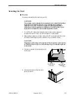
Страница 18: ...lled application cards 1 Turn Off the PC Disconnect cables for the monitor and any powered equipment to the PC Then lay the PC chassis on a flat surface 2 After waiting at least one minute remove the...

Страница 19: ...etwork access point 9 Plug in the power cable and power on the PC being careful not to touch any internal boards or components and verify that the LEDs function as follows refer to Appendix A to locat...

Страница 20: ...A for an illustration of the LEDs If the test fails Recheck or change the IRQ setting Check the seating of the card Installing the Network Driver After installing the card you must install the networ...

Страница 21: ...tem from the adapter menu and click on OK 8 Select Setup Verify the chosen base address and IRQ 9 Click on OK to return to the Drivers setup 10 Click on Close to end the Drivers setup 11 Click on OK t...

Страница 22: ...rmined base address 10 Click on OK 11 The drivers will now be copied from a drivers to the hard drive Windows 95 may prompt you for some files needed to complete the TCP IP stack installation These ar...

Страница 23: ...ypically if the software detects the HotWire DSL card you will see only one base address listed in the Available Base Address window This address matches the address set on the card and should match t...

Страница 24: ...your system when transferring or receiving data The default setting is 380 Interrupt No Signal used by your device to inform the CPU when the device wants to transfer or receive data The default setti...

Страница 25: ...r your card If necessary use to scroll the display The setting for the speed in this window must match the speed for the card For RADSL cards it is highly recommended that the Trasmit and Receive rate...

Страница 26: ...d you can use the following procedure to simply verify that the path is set appropriately Some other TCP IP package for example Chameleon Trumpet etc Locate the file in your file system and enter the...

Страница 27: ...If you attempt to save but the file cannot be found or you need to change the path refer to Checking Setting Protocol ini Path for information Procedure To save the configuration settings 1 Select Fi...

Страница 28: ...n address does not appear see Troubleshooting Tips on page 2 18 4 Select Card Status The window can be scrolled to provide the latest card status If the card is up and running the window displays the...

Страница 29: ...lict 2 Attempt to Reset Card as described in Chapter 3 3 Recheck that IRQ settings on card match software Cannot connect to Central Office IRQ conflict Network Link is Down Network cable is not connec...

Страница 30: ...twork This utility also provides the capability to download firmware and run diagnostic tests on the card when instructed by a central office technician To access the utility double click on the HotWi...

Страница 31: ...us The result of these operations will display in the text area of the window When a card is up and running the window shows the card status as shown in the example For window operations click on Exit...

Страница 32: ...atus Select Statistics from the Diagnostics menu to display the Statistics window You use this selection to view performance statistics on data transmissions and the state of the network For example t...

Страница 33: ...t data is looped back to the PC end of the connection only For window operation click on Start to start a test Refer to the following procedure Exit to close the window and return to the main menu wit...

Страница 34: ...The default is 10 Packet Size to indicate the size of packets to be tested The default is 64 bytes For window operation select the values to be used during the test and or click on OK to accept the p...

Страница 35: ...e Diagnostics Utility main menu The Open window appears This window uses standard Windows user interface conventions 2 Select the appropriate drive for example drive a as shown on the sample Open wind...

Страница 36: ...l LEDs The following illustration shows the location of the LEDs on the faceplate The table interprets the status of the card when the LEDs are on off or blinking 496 15015 1 2 3 4 5 6 7 8 1 2 3 4 5 6...

Страница 37: ...ng received TX Blinking On Off Normal operation Indicates presence of DSL traffic No data being sent System SYS Blinking Off On Self test in progress Occurs at power up Error condition Self test faile...

Страница 38: ...n Assignments B The following table defines the pinouts for the DSL connector It is a 6 pin non keyed modular jack female connector Table B 1 DSL Connector Pin Assignments Pin Use 1 NC 2 NC 3 RING 4 T...

Страница 39: ...tude and Phase Modulation RADSL multi speed or CAP ADSL 1 544 Mbps 2 048 Mbps downstream 64 kbps upstream interface to the local loop Digital Interface PC ISA bus and NDIS 2 01 3 0 compliant IP protoc...

Страница 40: ...Off Off Off Off 0x210 On Off Off Off Off On 0x220 On Off Off Off On Off 0x230 On Off Off Off On On 0x240 On Off Off On Off Off 0x250 On Off Off On Off On 0x260 On Off Off On On Off 0x270 On Off Off On...

Страница 41: ...ch 2 Switch 1 0x320 On On Off Off On Off 0x330 On On Off Off On On 0x340 On On Off On Off Off 0x350 On On Off On Off On 0x360 On On Off On On Off 0x370 On On Off On On On 0x380 On On On Off Off Off 0x...

Страница 42: ...ransmission over copper wire for both T1 and E1 services Worldwide interconnected networks that predominantly use the TCP IP protocol Areas of memory your CPU uses to distinguish between the various p...

Страница 43: ...ostics Utility 1 3 exiting 3 6 icon 3 1 installing 2 2 main menu 3 1 Digital Interface C 1 Digital Subscriber Loop iii DIP Switch on off position 2 4 SW1 2 4 SW2 2 5 SW3 2 5 Switches 7 8 2 5 Disk requ...

Страница 44: ...B 1 Protocol ini File 2 15 Protocol ini Path saving path 2 16 setting path 2 15 window 2 15 R RADSL Rate Adaptive Digital Subscriber Loop 1 2 RAM Requirements 1 3 Recommend Base Address 2 12 window 2...

Страница 45: ...Windows 3 1 network driver 2 9 version 1 3 Windows 95 installation procedure 2 11 network driver 2 9 version 1 3 Windows for Workgroups installation procedure 2 10 network driver 2 9 Protocol ini fil...

Отзывы: