


Installation and Setup
2-8
5100-A2-GB21-00
November 1996
5. Verify that the DIP switches on the HotWire
card are set to the proper settings.
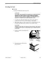
6. Insert the card into the expansion slot:
— Pick up the card by the edges or the
top corners. Be careful not to touch
the pins on the bottom of the card.
— Align the connector on the bottom of
the card, directly over the slot. Place
one hand along the top edge of the
card, directly over the connector
area, and push down firmly but
gently until the connector is fully
seated.
— To ensure that the card is properly
seated, gently try to lift the card.
7. Secure the card to the chassis using a bracket screw.
8. Insert the 6-pin plug on the provided
cable into the network access jack
on the card. Connect the other end of
the cable to the network access point.
9. Plug in the power cable and
power on the PC, being careful not to
touch any internal boards or components,
and verify that the LEDs function as
follows (refer to
Appendix A
to locate
the LEDs):
— The SYS LED turns solid green.
Refer to the Power-Up Self-Test
section following this procedure if
the SYS LED does not turn green.
— The CD LED blinks and then both the CD and LNK LEDs turn solid
green. This indicates that the card is communicating with the central
office unit, meaning your DSL link is operational. If the CD and LNK
LEDs do not function as stated, stop the installation process and
contact your customer service representative for assistance.
10. Turn the power Off again.
11. Replace and secure the cover to the PC.
12. Plug in the monitor and other peripheral devices you disconnected and power
on the PC.
16-Bit
ISA Expansion
Card Slot
8-Bit
ISA Expansion
Card Slot
496-14968
Push Down Firmly
496-14971
Network
Access
Jack
Hotwire
Card
Cable


