background image

There is a risk assumed by individuals who use this type of equipment. To minimize risk, please
follow these rules:

IMPORTANT NOTES

1. Consult your physician before beginning any exercise program.

Please note:

Tools Required for Assembly

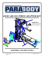
* Thank you for purchasing the Parabody 441101 Leg Press Adapter Kit. Please read these
    instructions thoroughly and keep them for future reference. This product must be assembled
    on a flat, level surface to assure its proper function.

* Rubber mallet or hammer
* 3/4” wrench
* 9/16” wrench
* Ratchet with 3/4” and 9/16” sockets
* 5/32” Allen wrench
* Adjustable wrench
* Tape measure

2

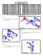
NOTE: BOLT LENGTH IS MEASURED FROM THE UNDERSIDE OF THE HEAD OF THE BOLT.

   BOLT LENGTH RULER:

3. Do not allow minors or children to play on or around this equipment.

2. Inspect equipment daily. Tighten all loose connections and replace worn parts immediately.
    Failure to do so may result in serious injury.

4. Exercise with care to avoid injury.

5. If unsure of proper use of equipment, call your local Parabody distributor or call the
    Parabody customer service department at (800) 328-9714.

* We recommend cleaning your product (pads and frame) on a regular basis, using warm soapy
   water. Touch-up paint can be purchased from your Parabody customer service representative
   at (800) 328-9714.

Bolt Length Ruler

0

1

2

3

4

5

6

1/2

1/2

1/2

1/2

1/2

1/2

BOLT LENGTH

Содержание 441101 440

Страница 1: ...441101 440 LEG PRESS ADAPTER KIT Part 7039101 REV B Revision 07 19 01 1 ASSEMBLY INSTRUCTIONS WARNING Read and follow all directions for each step to insure proper assembly of this product...

Страница 2: ...ustable wrench Tape measure 2 NOTE BOLT LENGTH IS MEASURED FROM THE UNDERSIDE OF THE HEAD OF THE BOLT BOLT LENGTH RULER 3 Do not allow minors or children to play on or around this equipment 2 Inspect...

Страница 3: ...T 3 8 X 3 BOLT 1 2 X 3 1 4 BOLT 110 3 4 CABLE ASSY 82 1 2 CABLE ASSY QTY 4 5 2 3 2 2 1 1 DESCRIPTION FRONT LEG PULLEY BRACKET CABLE SWIVEL BASE CONNECTION 3 1 2 PULLEY 2 SQ END CAP COVER CAP QUICK DIS...

Страница 4: ...and two 1 2 LOCKNUTS 12 See FIGURE 4 STEP 5 Remove one existing 3 1 2 PULLEY and two SPACERS from theADJUSTMENT TUBE on the 100 LEG PRESS OPTION by unfastening the 3 8 X 4 1 2 BOLT holding the pulley...

Страница 5: ...WASHERS 2 WHEELS AND NUT Note Securely tighten then back off 1 4 turn to allow the CABLE SWIVEL WHEELS to rotate freely See FIGURE 6 5 2 WHEEL 3 8 X 4 1 2 BOLT NUT 2 WHEEL STEP 7 Securely fasten the 1...

Страница 6: ...the threaded end of CABLE from the HEAD PLATE ASSEMBLY Route the LAT CABLE around the PULLEY BLOCK as shown in FIGURE 8 REMOVE CABLE FIGURE 8 The pulleys in TOP BOOM may need to be temporarily removed...

Страница 7: ...pulleys in TOP BOOM may need to be temporarily removed to perform this step Note Make sure the CABLE is running OVER the BOLTS connecting the FRONT UPRIGHT to the TOP BOOM These may also have to be r...

Страница 8: ...LE SWIVEL 3 with one QUICK DISCONNECT LINK 8 IMPORTANT Tighten the QUICK DISCONNECT LINK 8 securely 8 0 1 2 3 4 5 6 1 2 1 2 1 2 1 2 1 2 1 2 Route the 82 1 2 CABLE 17 under the WEIGHT STACK as shown in...

Страница 9: ...PULLEY BRACKET 2 as shown in FIGURE 12 STEP 13 Attach one 3 1 2 PULLEY 5 to the FRONT LEG 1 and one 3 1 2 PULLEY 5 to the BASE CONNECTION 4 using two 3 8 X 1 3 4 BOLTS 13 and two 3 8 LOCKNUTS 11 Note...

Страница 10: ...IGHT STACK PIN Thread the 110 3 4 CABLE 16 into the HEAD PLATE ASSEMBLY until the PULLEY BRACKET 2 is held against the TOP BOOM and the cable is slightly pulling up on the HEAD PLATE Tighten the jan b...

Отзывы: