
128-9239
3 of 24
Page 3
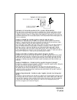
NOTE:
Do not remove the fuse holders from this wire harness. Fuses must be
used and located as close as possible to the power source for adequate
protection of the vehicle.
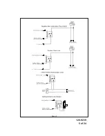
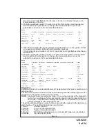
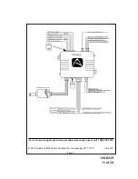
WIRING THE 6 PIN MAIN POWER HARNESS Connector (P/N 4120110)
Fused Red/White Trace Wire:
+ 12 Volt Battery 1 Source 20A Max
Locate the vehicle battery wire(s) at the ignition switch. Verification: These wires will register
voltage in all positions of the ignition switch. Connect the Red w/White wire to the vehicle's battery
wire. This wire provides power for the control circuit as well as the ignition 1 and ignition 2 relays.
Fused Red Wire:
+ 12 Volt Battery 2 Source 30A Max
Locate the vehicle battery wire(s) at the ignition switch. Verification: These wires will register
voltage in all positions of the ignition switch. Connect the Red wire to the vehicle's battery wire.
This wire provides power for the start relay and the accessory relay.
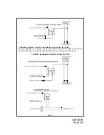
Purple Wire:
Starter Output
Careful consideration for the connection of this wire must be made to prevent the
vehicle from starting while in gear. Understanding the difference between a me-
chanical and an electrical Neutral Start Switch will allow you to properly identify
the circuit and select the correct installation method. In addition you will realize
why the connection of the safety wire is required for all mechanical switch con-
figurations.
Failure to make this connection properly can result in personal injury and property damage.
In all installations it is the responsibility of the installing technician to test the remote start
unit and ensure that the vehicle cannot start via RF control in any gear selection other than
park or neutral.
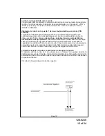
In both mechanical and electrical neutral start switch configurations, the connection of the
Purple wire will be made to the low current start solenoid wire of the ignition switch harness.
This wire will have +12 Volts when the ignition switch is turned to the start (crank) position
only. This wire will have 0 Volts in all other ignition switch positions.
Pink Wire:
Ignition 1 Output
Connect this wire to the ignition 1 wire from the ignition switch. This wire will show +12 Volts
when the ignition key is turned to the "ON" or "RUN" and the "START" or CRANK"
positions, and will have 0 Volts when the key is turned to the "OFF" and "ACCESSORY"
positions.
Pink/White Wire:
Ignition 2 Output
Connect this wire to the ignition 2 wire from the ignition switch. This wire will show
+ 12 Volts when the ignition key is turned to the "ON" or "RUN" position and is some cases
the "START" or CRANK" position. This wire will show 0 Volts when the key is turned to the
"OFF" and "ACCESSORY" positions.
NOTE:
See programming information (Bank 3 Selection # 6) concerning this wire to allow
output during the "START" mode.
Содержание PA-420C
Страница 5: ...128 9239 5 of 24 Page 5...


