background image


SMARTZONE UPS USER MANUAL 


32 


Screen # 

Parameter(s) Name(s) 

Example Display Content 

M-01A 

(LI) 

Input Voltage & Output 

Voltage 

(Normal Mode) 


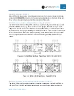
The above page is an example of a Li 120V voltage monitoring page for the Line 
Interactive UPS system. The power diagram shows that the unit is operating in 
Normal state with no Automatic Votlage Reulation (AVR). 

Note:

 Normal state for 

the Line Interactive UPS is to bypass the rectifiy and invertor circuitry. 

M-01A 

(LI) 

Input Voltage & Output 

Voltage 

(Normal Mode with AVR 

Active) 


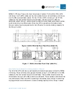
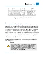
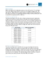
The above page is an example of a Li 120V voltage monitoring page for the Line 
Interactive UPS system. The power diagram shows that the unit is operating in the 
Normal state with Automatic Voltage Regulation (AVR). 

M-01B 

(DC) 

Input Voltage & Output 

Voltage 


(ECO Mode)


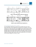
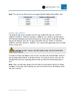
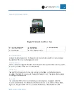
The above page is an example of a Li 230V voltage monitoring page for the 
double conversion UPS system. The power diagram shows that it is operating in 
the ECO State. 

Содержание smartzone 1-3KVA

Страница 1: ...User Manual V3 2 Uninterruptible Power Supply 1 3KVA SINGLE PHASE...

Страница 2: ...10 UPS States 12 Normal State 12 ECO State 12 CF State 12 Gen State 12 AVR State 13 Battery State 13 Bypass State 13 Fault State 13 Battery Test State 14 UPS Physical Features and Accessories 15 Phys...

Страница 3: ...Down the UPS 31 Color Display Operation 31 Monitor Operation 31 Setup Operation 37 Double Conversion VRLA UPS 38 Double Conversion Li UPS 42 Line Interactive Li UPS 46 Appendix A 1 to 3kVA Fault Code...

Страница 4: ...e units is either on line double conversion with a built in economy ECO mode or line interactive The on line double conversion topology supplies the best power conditioning by recreating a true sinewa...

Страница 5: ...es reliability performance self protection and self diagnostics User Friendly Color Display with Color Status LEDs allow the user to easily set operational parameters and get UPS status Intelligent Mo...

Страница 6: ...planation of the UPS working modes and operating states This block diagram is not the actual block diagram of the UPS units Double Conversion Overview The UPS input is connected to an AC power source...

Страница 7: ...modes This section explains these settable working modes The UPS working mode is manually configured into the UPS at setup time The selected mode will become the Default state of the UPS until the wo...

Страница 8: ...arm Refer to Appendix C State Transitions Based on External Events for state transitions based on input output events Note This unit does have short circuit protection but only when power is being pro...

Страница 9: ...the on line double conversion UPS units When the UPS is in Normal mode and the power requirements for the load are not critical and the input source is stable no power anomalies the UPS may be set to...

Страница 10: ...ate when a short circuit occurs on the output of the UPS the UPS unit may be damaged Convert Frequency CF Mode This mode is only supported on the on line double conversion UPS units The UPS may be set...

Страница 11: ...n the 1 3kVA UPS unit is powered OFF and restarted the units will restart in Normal mode If the input power is lost or has input anomalies outside of the operating range of the UPS while the UPS is op...

Страница 12: ...now in the Battery state The UPS will continue to provide power to the load for a limited time runtime of the battery backup system connected to the UPS for the percentage of load connected If an inte...

Страница 13: ...ECO State The UPS will go into the ECO state when the UPS is set to ECO Mode at setup time If the UPS is set for ECO Mode the ECO state is the default state where the UPS will return to after the int...

Страница 14: ...e recovers If an internal or external output event occurs while operating in the battery state the output will shut down AC power to the load will be lost Bypass State The UPS may automatically transi...

Страница 15: ...est may have an impact on the battery life All battery tests are preset for a duration of 10 seconds The user can select the frequency of the test The battery test may be automated through the network...

Страница 16: ...st remain clean and clear of all objects that may restrict the air flow through the UPS unit Status LEDs Each unit has four Status LEDs Normal LED green Battery LED yellow Bypass LED blue and Alert LE...

Страница 17: ...input circuit breaker to protect form overload conditions labeled BREAKER with a line to the input interface on the back of the unit Refer to the corresponding Customer Documentation for details Outp...

Страница 18: ...PLUG WILL BE WIRED TO A REMOTE NORMALLY CLOSED DRY CONTACT TO PROVIDE A SHORT FOR NORMAL OPERATION THE REMOTE DRY CONTACT COULD BE OPENED TO COMMAND THE UPS TO SHUT DOWN IN AN EMERGENCY DB9 Coms Port...

Страница 19: ...outlets Group 1 4x 5 15R outlets are the main outlets that are not switchable These outlets should contain the critical loads Group 2 2x 5 15R are switchable outlets These outlets could contain the n...

Страница 20: ...be programmed to turn off earlier to conserve battery capacity for the Group 1 outlets Figure 6 2kVA VRLA NA Rear Panel View U02x11V Figure 7 1 5kVA Li NA Rear Panel View U02x11L 3kVA North America M...

Страница 21: ...nnector on the other end Either one of these input cords may be plugged into the input C14 plug on the back of the UPS unit This unit has two groups of outlets Group 1 4x C13 is the main non switchabl...

Страница 22: ...e Group 2 outlets may be programmed to turn off earlier to conserve battery capacity for the Group 1 outlets Figure 11 2kVA VRLA Li EU Rear Panel View 3kVA Europe Models Rear Panel U03x12V U03x12L The...

Страница 23: ...ill increase the runtime by at least 3 times Each battery cartridge holds 2 3 4 or 6 12Vdc batteries connected in series depending on the battery cartridge voltage A total of three wires are connected...

Страница 24: ...lace the battery cartridge sets for all EBP units connected to the UPS The following table provides the battery cartridge part number that must be used with the specific UPS part number UPS Unit SKU B...

Страница 25: ...he S type model UPS units ex U01S11V U02S12V U03S11V U01S12L U02S11L U03S12L etc may be field upgradable with a network card or a relay card CAUTION DO NOT TOUCH THE NETWORK CARD WITHOUT PROPER ESD PR...

Страница 26: ...sor connection supports Panduit environmental sensors and or the sensor hub with the cables provided in the sensor installation kit MAC ID Label The MAC ID of the wired ethernet port is listed on the...

Страница 27: ...nnector provides a COM port connection for configuration via a command line interface CLI to the Network card Refer to the Network card User s Manual for more details on the operations of the Network...

Страница 28: ...would change from NC Normal Closed to Open 10 Bypass active Close When the UPS is working in the Bypass state Pin 1 to Pin 10 would change from NO Normal Opened to Close 11 UPS fault Open When the UPS...

Страница 29: ...h unit has four Status LEDs that provide a quick high level view of the unit s operating conditions LED Icon LED Name Color Operating Condition Alert LED Yellow Unit has an Active Warning Alert Red Un...

Страница 30: ...Operation without changing any settings Monitor Operation while in Battery state press for 3 6 seconds first audio beep to turn the UPS OFF Monitor Operation while in Normal state press for 3 6 secon...

Страница 31: ...ld the ENTER ON MUTE button until the first audio beep is heard about 3 6 seconds When test passes the UPS unit is ready to be setup for service Cold Starting the UPS Start the UPS on Battery CAUTION...

Страница 32: ...up Operation mode Use the function buttons from above to transition between the two modes of operation Monitor Operation There are seven Monitor Operation pages Monitor Operation mode is default scree...

Страница 33: ...he Line Interactive UPS is to bypass the rectifiy and invertor circuitry M 01A LI Input Voltage Output Voltage Normal Mode with AVR Active The above page is an example of a Li 120V voltage monitoring...

Страница 34: ...ating in the CF State M 01D DC Input Voltage Output Voltage Generator Mode The above page is an example of a Li 230V voltage monitoring page for the double conversion UPS system The power diagram show...

Страница 35: ...ime in the center brackets may appear on any Monitor Operation page when the UPS is in the Battery state M 03 DC Input Frequency Output Frequency Normal Mode The above page is an example of the freque...

Страница 36: ...em that is operating in the Normal State M 04 LI Actual Power kW Apparent power kVA Normal Mode The above page is an example of the output power monitoring page on a Li Line Interactive UPS system tha...

Страница 37: ...e Interactive system that is operating in the Normal State M 06 DC UPS Partial Part Number Normal Mode The above page is an example of the Part Number monitoring page on a VRLA Double Conversion syste...

Страница 38: ...al error the UPS will also transion to the Bypass state M 07 LI Base UPS Core FW Version Alert Code Alarm Faults Normal mode The above page is an example of the Core Firmware Version monitoring page o...

Страница 39: ...lue Move to another Setup page if desired by pressing the UP or DOWN button Repeat the above process for that Setup value Note The Setup Operation mode will automatically close and not save any Setup...

Страница 40: ...units S 02 Output Voltage setting 100 110 115 120 125 220 230 240 The default Output Voltage setting is 120V for North American UPS units and 230V for European UPS units For maximun efficiency set the...

Страница 41: ...group of outlets may be configured to turn OFF before the Group 1 outlets The lower the voltage setting the longer outlet Group 2 will stay ON while the UPS is running on battery However the longer t...

Страница 42: ...76Vac for European UPS units These values my be changed in 1Vac increments decrements This value should be set to the minimum voltage that the connected loads will tolorate Increasing this voltage may...

Страница 43: ...l not be allowed to transition to the Bypass State under any circumstances Double Conversion Li UPS These UPS units are for the European market only The double conversion Li UPS has eight Setup pages...

Страница 44: ...g is Normal mode for all Double Conversion UPS units S 02 Output Voltage setting 220 230 240 The default Output Voltage setting is 230V for European UPS units For maximun efficiency set the output vol...

Страница 45: ...ing the longer outlet Group 2 will stay ON while the UPS is running on battery However the longer this outlet group stays ON the less runtime there is for outlet Group 1 which may contain the critical...

Страница 46: ...is value should be set to the minimum voltage that the connected loads will tolorate Increasing this voltage may limit the UPS from switching to bypass when the input voltage is low S 07A Buzzer setti...

Страница 47: ...e allowed to transition to the Bypass state under any circumstances Line Interactive Li UPS These UPS units are for the North American markets only The Line Interactive Lithium Ion UPS has five Setup...

Страница 48: ...tting 100 110 115 120 125 The default Output Voltage setting is 120V for North American UPS units For maximun efficiency set the output voltage to the input source voltage Note The output voltage must...

Страница 49: ...t group turns OFF The lower the percentage setting the longer outlet Group 2 will stay ON while the UPS is running on battery However the longer this outlet group stays ON the less runtime there is fo...

Страница 50: ...Red Alert On Reboot the UPS unit 9 Fan Fault Critical Continuous Red Alert On Remove ventilation obstructions Reboot the UPS unit 12 InitializationFault Critical Continuous Red Alert On Reboot the UP...

Страница 51: ...ic Yellow Alert On Reduce the output load 33 No Battery Detected Warning Periodic Yellow Alert On Ensure that the battery connector is properly seated and makinga good connection Allow the Battery to...

Страница 52: ...to Trace Warning Periodic Yellow Alert On Ensure that the source input voltage and frequencyare within the UPS operatingrange 45 EPO Activated Warning Periodic Yellow Alert On Ensure that the EPO por...

Страница 53: ...connected 3 The UPS does not indicate any failure but there is no output voltage The output breaker is not turned ON if applicable Turn ON the output breaker if applicable The output cable is not sec...

Страница 54: ...e 0 C Battery over temperature protection was triggered Ensure that the UPS and EBP are operating in an environment at or below 40 C 10 Battery backup time is shorter than nominal The battery cartridg...

Страница 55: ...to the Battery state CF state Frequency Range If the input frequency goes outside of this range the UPS will transition to the Battery state Bypass state Frequency Range If the input frequency goes ou...

Страница 56: ...tion back to the Normal or Gen state If the input voltage goes below the Boost range or above the Buck range then the UPS will transition to the Battery state CF ECO Mode Voltage Range NA NA Normal st...

Страница 57: ...no load Disconnect the battery cartridge s from the system see InstallationManual Store transport the product in the upright orientation in normal packagingin a dry environment Duringstorage recharge...

Отзывы: