background image

35/36

USER AND MAINTENANCE MANUAL  I ENG_OMM_CD100_P07 I 2022-10-19 


@Pandrol 2022


12. 

Warranty And Service

12.1. 

Warranty

All products from Pandrol AB are supplied with a 12 month Warranty.
The Warranty is not valid if the indicated defect or fault in the product does not exist or if the 

fault is the result of a handling error, tampering or non-permitted modification, or if the machine 

has been exposed to fire, lightning or excess voltage.

12.2. Service

Aftersales support and technical service are available from Pandrol AB, Sweden, during and 

after the Warranty period. Please contact Pandrol AB.

12.3. Disclaimer

Pandrol AB exempts itself from liability in the event of usage that deviates from that 

recommended in this manual.

12.4. Contact

Address

Phone

Internet and E-mail

Pandrol AB

Hyggesvägen 4

824 35 Hudiksvall

SWEDEN

+46 650 165 05

www.pandrol.com

[email protected]

12.5. Declaration Of Conformity

A declaration of conformity is attached (CE certification).The declaration is a proof that the tool 

is CE approved.

12.6. 

Recycling and Environment

Sustainable environment is a great part of Pandrol. All components of the Power unit can either 

be:
•  Recycled
•  Taken care of
•  Be re-used
We recommend you to follow your local region regulations of environmental and recycling 

policies

At the end of their useful life, discard batteries with due care for our environment. The battery 

contains material which is hazardous to you and the environment. It must be removed and 

disposed of separately at a facility that accepts lithium-ion batteries.This product must not be 

disposed of with normal household waste. Should you find one day that your product needs 

replacement, or if it is no further use to you, do not dispose of it with household waste. Make 

this product available for separate collection.

12.7. 

Disposal Of Battery

Содержание CD100

Страница 1: ...Partners in excellence ENG_OMM_CD100_P07 2022 10 19 USER AND MAINTENANCE MANUAL CD100 CD100 B...

Страница 2: ...2 36 USER AND MAINTENANCE MANUAL I ENG_OMM_CD100_P07 I 2022 10 19 Pandrol 2022...

Страница 3: ...the right to change specifications equipment instructions and maintenance guidelines without prior notice The manual contains instructions about the following topics 1 Installation 2 Operation 3 Safet...

Страница 4: ...hnical Data Battery Power Unit 6000617 12 4 Tools 13 4 1 Clipping Tool 1100201 13 4 2 De clipping Tool 1100058 FE FCX 5012730 14 5 Transport And Packaging 15 5 1 Unpacking The Power Unit 15 5 2 Unpack...

Страница 5: ...27 9 1 Clipping And Declipping Connect Rail To Sleeper 28 9 2 De Clipping Disconnect Rail From Sleeper 29 9 3 After Operation 29 10 Maintenance 30 10 1 Power Unit 30 10 2 Clipping And De clipping Tool...

Страница 6: ...own safety and expose yourself to a serious accident or injury risk Before each start perform a general inspection of all parts and make sure that they are not worn damaged or loose Also make sure th...

Страница 7: ...ual before use art 710016 Wear safety googles art 710017 Wear safety helmet art 710018 Wear hearing protection art 710019 WARNING Oil pressure art 710216 WARNING Risk of crushing art 710217 High volta...

Страница 8: ...g on The equipment must be serviced maintained or in any way repaired only by qualified personnel who are familiar with both this Operation Maintenance Manual and the Honda manual and have received tr...

Страница 9: ...0 consists of a motor unit a handlebar a fastening tool and a declipping tool according to 2 4 5 and 6 in the table below CD100 B consists of a drive unit a handlebar a fastening tool and a declipping...

Страница 10: ...r Unit is based on Honda original parts and the working tools are based on well known Pandrol technology The Power Unit is supported by a steel wheel to the rail which relieves the operator from the w...

Страница 11: ...ion emission Measuring point Operating condition Measured vibration emission value Handle bar Idle running 0 53 m s2 Measuring point Operating condition Measured vibration emission value Handle bar Fu...

Страница 12: ...st and easy connection to the working tools The Drive Unit is supported by a steel wheel to the rail which relieves the operator from the weight and thus prevents the operator from wearing injuries Th...

Страница 13: ...Length 480 mm Width 260 mm Height 400 mm Weight 19 kg Packaging dimensions Length 390 mm Width 580 mm Height 450 mm Weight 29 kg Battery Battery capacity 432 Wh 6 Ah 72 V Work capacity 300 clips charg...

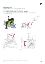
Страница 14: ...onnectors 4 Bracket 5 Claws Fig 12 Clipping tool Technical data for the Clipping Tool part no 1100201 Decription Specification Attachment to Power Unit part no 5014188 or Battery Drive Unit art nr 600...

Страница 15: ...ism 5 Bracket 6 Claw Technical data for the De clipping Tool part no FC 1100058 FE FCX 5012730 Decription Specifikation Attachment to Power Unit part no 5014188 or Battery Drive Unit art nr 6000617 Ca...

Страница 16: ...safe to transport store and carry Follow the instructions in the reversed order when storing the components The pictures are for illustration only the appearance of the machine may vary 5 1 Unpacking...

Страница 17: ...Figur 19 17 36 USER AND MAINTENANCE MANUAL I ENG_OMM_CD100_P07 I 2022 10 19 Pandrol 2022 Fig 18 Fig 19 Fig 20 Fig 21...

Страница 18: ...6 USER AND MAINTENANCE MANUAL I ENG_OMM_CD100_P07 I 2022 10 19 Pandrol 2022 5 2 Unpacking The Clipping Tool Fig 22 Clipping Tool in its suitable box Fig 23 Easy to lift up and to store when not being...

Страница 19: ...page 17 On ground transport for private use or transport carried out by an employee or an inhouse company transport service from company site to working site does not require lithium battery mark and...

Страница 20: ...aulic oil and fuel according to the manual before starting the engine 6 1 1 Engine oil and fuel CD100 Read the Honda manual for further information enclosed with the Power Unit 6 1 2 Hydraulic oil CD1...

Страница 21: ...pping Tool with the arms on each side of the rail Disconnect the Handle Bar Unit from the Power Unit Fasten steering bar to the Clipping Tool using the locking mechanism Fasten the Power Unit to the C...

Страница 22: ...6 3 De clipping Tool Place the De clipping Tool with the arms on each side of the rails Disconnect the Handle Bar Unit from the Power Unit 1 Fasten the Handle Bar Unit to the De clipping Tool Fasten t...

Страница 23: ...the SETUP INSTALLATION section Start the engine drive unit Accelerate slowly to prepare for clipping de clipping When the claws are in the proper position against the clips adjust the wheel with the...

Страница 24: ...apted to the purpose 5 Install the first two FASTCLIP 6 Check that the FASTCLIP is correctly installed The FASTCLIP must be in the position recommended by Pandrol Measure its position and compare with...

Страница 25: ...ps to accomodate correct for different rail heights 7 5 Adjustments Of Claws The claws are adjustable in three different positions 1 Loosen the screws on the lower part of the claws Those screws are i...

Страница 26: ...he engine power unit according to assembly instructions Connect the hydraulic hoses make sure that they are clean prior to connection Ensure that you are using correct claws and arms Switch the ON OFF...

Страница 27: ...Make sure that the claws are placed in a proper position relative to the clip 4 Make sure there is a space of 1 2 mm between the clips and the claw when positioning the de clipping pads for an optimal...

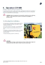
Страница 28: ...position To release the battery press the red button 1 Fig 45 WARNING Read all safety warnings and all instructions Failure to follow the warnings and instructions may result in electric shock fire an...

Страница 29: ...that you are using correct claws and arms 2 Press the button 1 once to power up the drive unit 3 Press the activation button 3 once to activate the tool 4 Lift the machine slightly and move the tool a...

Страница 30: ...ress the button 1 once to power up the drive unit 3 Press the activation button 3 once to activate the tool 4 Lift the machine slightly and move the tool along the rail so that the arms are positioned...

Страница 31: ...rts and spares delivered by Pandrol AB WARNING All adjustments work overhaul and service must take place with the engine turned off cooled down and with working tools disengaged Failure to do so could...

Страница 32: ...ws and nuts Check tighten if needed X Entire unit Check for oil leakage X Locking mechanism Lubricate with oil spray X Hydraulic cylinder Lubricate with grease X Bolts Lubricate with oil spray X Slidi...

Страница 33: ...33 36 USER AND MAINTENANCE MANUAL I ENG_OMM_CD100_P07 I 2022 10 19 Pandrol 2022 10 3 2 De clipping tool Fig 53 Fig 54...

Страница 34: ...AB we mainly use steel screws and nuts The table below shows the nominal tightening torque in Nm for the screws and nuts that are used These torques do not apply to wheel bearings Thread diameter Tig...

Страница 35: ...l SWEDEN 46 650 165 05 www pandrol com info rosenqvistrail pandrol com 12 5 Declaration Of Conformity A declaration of conformity is attached CE certification The declaration is a proof that the tool...

Страница 36: ...Find out more at pandrol com Pandrol AB Hyggesvagen 4 824 34 Hudiksvall Sweden 46 650 16505 info rosenqvistrail pandrol com Pandrol Partners in excellence...

Отзывы: