manualshive.com logo in svg
background image

Left Button

Set Button

Right
Button

Down
Button

Up
Button

Up Button 

(

J

)

:

Moves the cursor upwards.  Use this button to select an item or adjust
the parameters.

Down Button 

(

K

)

: Moves the cursor downwards.  Use this button to select an item or

adjust the parameters.

Right Button 

(

M

)

:

Moves the cursor to the right.  Use this button to select or adjust the
parameters of the selected item.  The parameter changes each time
this button is pressed.

Left Button 

(

L

)

:

Moves the cursor to the left.  Use this button to select or adjust the
parameters of the selected item.  The parameter changes each time
this button is pressed.

Set Button 

(

I

:

Executes selections and displays a submenu for an item with the 

N

mark.

• To reset the parameter to the factory default setting, move the cursor to the parameter

to be reset and press 

L

and 

M

simultaneously.

• To return to the previous menu or page, move the cursor to RET and press 

I

.

• To close the setup menu, move the cursor to END and press 

I

.

• All Reset Operation

All reset allows you to reset all setup menu items to the factory default settings if you are
unsure about the correct settings.  Proceed as follows:

(1) Make sure that the CAM SET UP menu is not displayed (a camera picture is displayed).
(2) While pressing both 

L

and 

M

, press 

I

for a few seconds.  The message ALL

RESET momentarily appears on the monitor screen.
This resets all adjustments and parameters to the factory default settings.

• Editing the CAM SET UP Menu

Important Notice:

When SET UP DISABLE appears in the bottom line of the CAM SET UP menu, you can-
not change the currently active settings.  This is to prevent accidental changing of the
settings.

To edit the CAM SET UP menu (change
settings), press 

J

and 

K

or 

L

and

M

to move the cursor to SET UP DIS-

ABLE in the bottom line.
Press 

I

.  SET UP DISABLE changes to

SET UP ENABLE.  Move the cursor to
END, then to the item(s) you want to
change.

Important Notice:

When the setup menu is closed after changing the parameters in the menu, the new
values are stored in the EEPROM (Electrically Erasable and Programmable Read-Only
Memory).  These values remain valid until new values are stored, even if the power of
the camera is off.

    ** CAM SET UP **
CAMERA ID    OFF    
ALC/ELC      ALC    
SHUTTER      ---
AGC          ON(DNR-H)
SENS UP      OFF
SYNC         INT
WHITE BAL    ATW1
MOTION DET   OFF    
LENS DRIVE   DC

 END     SET UP DISABLE

    ** CAM SET UP **
CAMERA ID    OFF    
ALC/ELC      ALC    
SHUTTER      ---
AGC          ON(DNR-H)
SENS UP      OFF
SYNC         INT
WHITE BAL    ATW1
MOTION DET   OFF    
LENS DRIVE   DC

 END     SET UP ENABLE

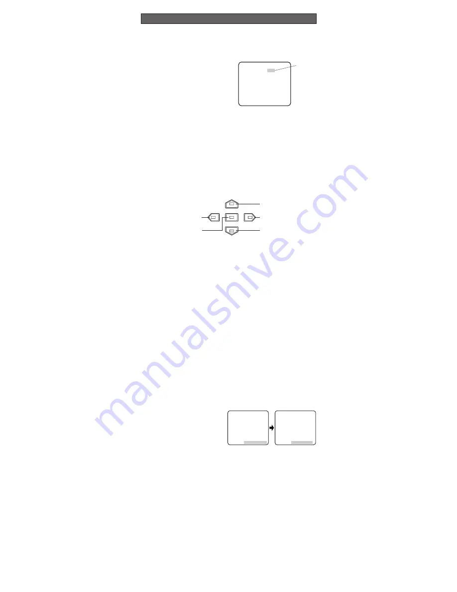
1. CAMERA SETUP MENU

This camera utilizes an on-screen user setup menu.

• Opening the Setup Menu

Press and hold down 

I

for 2 seconds or

more.

The CAM SET UP menu appears on the
monitor as shown in the figure.
Check the current settings on the menu.

Refer to the following sections for a detailed
description of menu items. If you decide not to make any changes after checking the cur-
rent settings, move the cursor to END in the bottom line, and press 

I

to close the setup

menu.

Note:

If no button is pressed for 6 minutes while any of the setup menu is being displayed

on the monitor screen, it is automatically closed and the mode returns to the normal
camera picture.

2. SETUP OPERATION

This camera utilizes an on-screen user setup menu (CAM SET UP).  To set items on the
CAM SET UP menu, use the following buttons on the side panel.

SETUP

    ** CAM SET UP **
CAMERA ID    OFF    
ALC/ELC      ALC    
SHUTTER      ---
AGC          ON(DNR-H)
SENS UP      OFF
SYNC         INT
WHITE BAL    ATW1
MOTION DET   OFF    
LENS DRIVE   DC

 END     SET UP DISABLE

Highlighted

Содержание WV-CP470 Series

Страница 1: ...to constitute a risk of electric shock to persons The serial number of this product may be found on the top of the unit You should note the serial number of this unit in the space provided and retain this instruction as a permanent record of your purchase to aid identification in the event of theft Model No Serial No SA 1966 SA 1965 N1101 1121 V8QA5915BN Printed in Japan N 19 Panasonic s WV CP470 ...

Страница 2: ...ith a 4 pin male connector supplied as a standard acces sory Part No YFE4191J100 w Flange back Adjusting Ring Adjusts the back focal length and picture focus e Flange back Fixing Screw r Lens Option t Camera Mounting Screw Hole Mounts the camera onto a mounting bracket y Down Button K Moves the cursor downward and selects items in the CAM SET UP menu u Left Button L Moves the cursor to the left se...

Страница 3: ... V AC power supply cord can be connected to this terminal The camera detects the power source auto matically 1 2 GND 1 2 AC 24V IN DC 12V IN 12 V DC 10 8 V 16 V Copper wire 24 22 20 18 size AWG 0 22mm2 0 33mm2 0 52mm2 0 83mm2 Resistance 0 078 0 050 0 030 0 018 Ω m Resistance 0 026 0 017 0 010 0 006 Ω ft Resistance of copper wire at 20 C 68 F Calculation of maximum cable length between camera and p...

Страница 4: ...ns less than 450 g 0 99 lbs can be mounted on the camera If the lens is heavier both the lens and camera should be secured by the supporter C mount Less than 13 mm 1 2 CS mount Less than 8 mm 5 16 MOUNTING LENS FOCUS ADJUSTMENT Mounting from the Top Remove the mount adapter from the bottom of the camera by removing the two fixing screws Attach the mount adapter to the top as shown in the figure th...

Страница 5: ...ing of the settings To edit the CAM SET UP menu change settings press J and K or L and M to move the cursor to SET UP DIS ABLE in the bottom line Press I SET UP DISABLE changes to SET UP ENABLE Move the cursor to END then to the item s you want to change Important Notice When the setup menu is closed after changing the parameters in the menu the new values are stored in the EEPROM Electrically Era...

Страница 6: ...ss I The ALC CONT menu appears 2 Move the cursor to SUPER D2 and select ON 3 If you want to adjust the video output level move the I cursor for LEVEL Adjust to the desired level by pressing L or M ALC CONT BACK LIGHT COMP SUPER D2 ON LEVEL I RET END 1 Camera Identification CAMERA ID Setting You can use the camera identification CAMERA ID to assign a name to the camera The camera ID consists of up ...

Страница 7: ...tically controls the gain an image brightness level Move the cursor to AGC and select automatic level adjustment ON DNR H ON DNR L or OFF The factory default setting is ON DNR H ON DNR H This setting raises the gain and brightens the image under low light con ditions ON DNR L This setting reduces an afterimage sometimes caused by a moving object when ON DNR H is activated OFF This setting does not...

Страница 8: ...urb synchronization 4 After confirming that the cursor is on EXT VBS press I The phase adjustment menu appears on the moni tor screen 5 Supply the video output signal of the camera to be adjusted and the refer ence gen lock input signal to a dual trace oscilloscope 6 Set the oscilloscope to the horizontal rate and expand the horizontal sync portion on the oscilloscope 7 Move the cursor to H PHASE ...

Страница 9: ...ity of the vertical phase of the camera video output signal may be disturbed 7 White Balance Setting WHITE BAL 7 1 Auto Tracing White Balance Mode ATW You can select one of three modes for white balance adjustment as follows The factory default setting is ATW1 ATW1 Auto Tracing White Balance 1 Move the cursor to WHITE BAL and select ATW1 In this mode the color temperature is monitored continuously...

Страница 10: ...enu to prevent misinterpretation under low light con ditions with noise It takes about 0 2 seconds for the alarm signal to reach the VCR s alarm terminal after the camera detects the moving object The motion detector is not specifically intended to prevent theft or fire 9 Lens Drive Signal Selection LENS DRIVE This item is used to select the type of auto iris lens drive signal to be supplied to th...

Страница 11: ...larm connections ON Black and white mode enabled OFF Color mode enabled The factory default setting is OFF 3 Select AUTO1 or AUTO2 using L or M 4 Press I The AUTO1 or AUTO2 menu appears on the monitor screen 5 Move the cursor to LEVEL and select the illuminance level using L or M LOW Color picture switches to black and white picture at approx 1 lx with F1 4 lens HIGH Color picture switches to blac...

Страница 12: ...Hz 4 8 W Power Consumption WV CP474 24 V AC 60 Hz 4 3 W 12 V DC 440 mA Dimensions without lens 70 mm W x 55 mm H x 118 mm D 2 5 8 W x 2 3 16 H x 4 5 8 D Weights without lens WV CP470 0 46 kg 1 lbs without power cord WV CP474 0 45 kg 1 lbs Weights and dimensions indicated are approximate Specifications are subject to change without notice SPECIFICATIONS OPTIONAL ACCESSORIES Lenses WV LA2R8C3B WV LA...

Отзывы: