
38
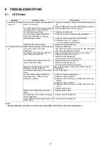
9 TROUBLESHOOTING
9.1.
LED Status
Note: *
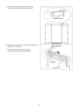
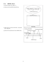
Disassembling the unit will be required to remove the USB cable from the unit and/or reassemble it.
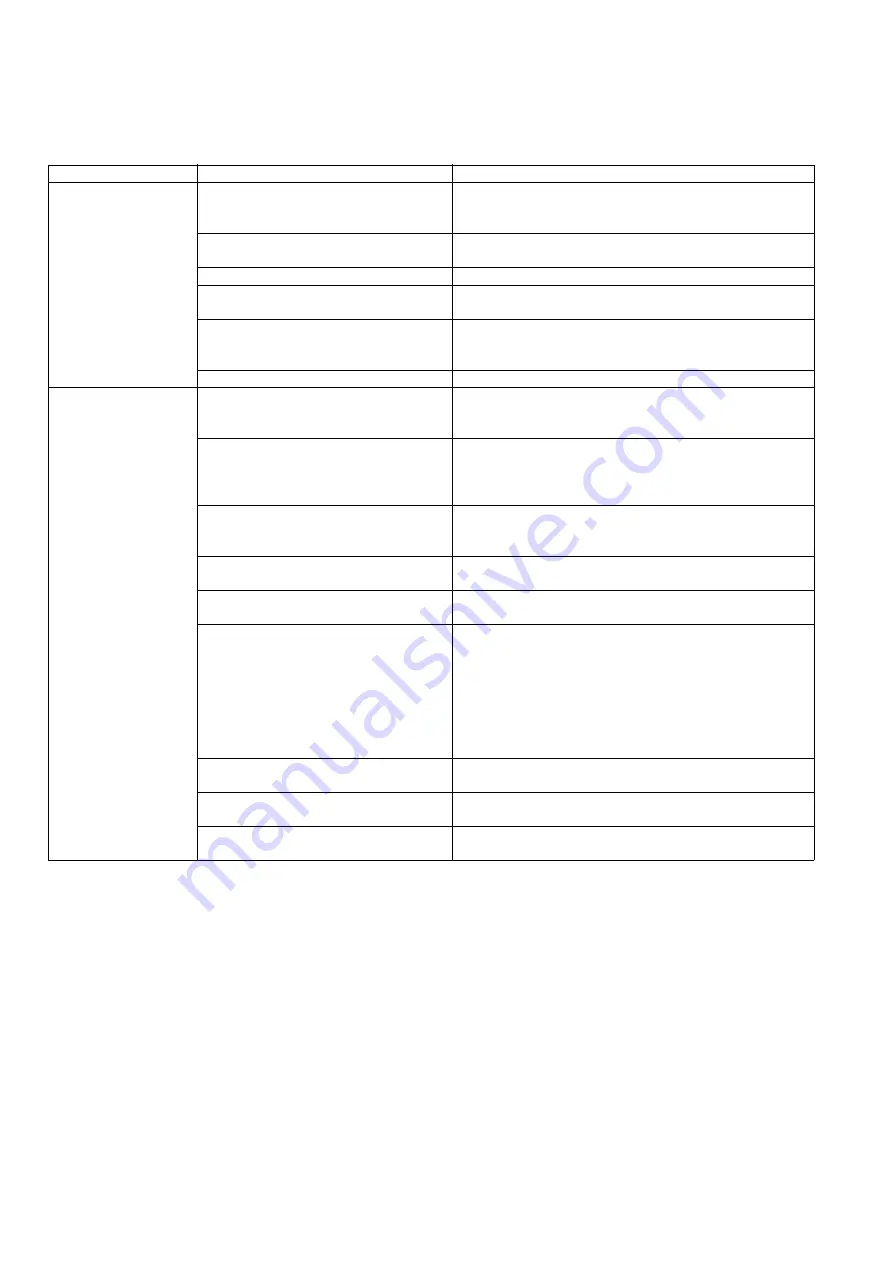
Symptom
Possible Cause
Check Point
1. The Status LED does
not light up.
The connection between elite Panaboard
and PC is not proper.
*
1. Check the connection between the elite Panaboard and
PC.
2. Plug the USB cable to another USB interface on the PC
The USB cable from the elite Panaboard
is connected to PC via a USB Hub.
1. Plug the USB Cable to the PC, directly.
The USB cable has a failure.
*
1. Replace the USB cable.
The connection between CONTROL
Board and LED Board is not proper.
1. Check the connection between CN4 and CN200
LED Board has a failure.
1. Check the following signal on the LED Board.
(1) CN200-3rd pin: + 5 V (Approx.)?
=> If yes, replace the LED Board.
CONTROL Board has a failure.
1. Replace the elite Panaboard.
2. The Status LED turns
red.
USB cable was plugged in while touching
the screen surface on the elite
Panaboard.
1. Unplug the USB cable.
Then, after 5 seconds or more, plug the USB cable again
without touching the screen surface
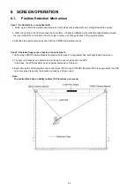
The reflection tape attached inside the
screen frame becomes dirty.
1. Clean the reflection tape around the screen frame
2. Replace the tape with a new one.
3. Restart the elite Panaboard.
Then check that the LED turns green.
The reflection tape is peeled from the
inside of the screen frame.
1. Replace the tape with a new one.
2. Restart the elite Panaboard.
Then check that the LED turns green.
Magnets or similar objects have been
attached to the Screen Board.
Remove the magnets or other similar objects from the
Screen Board.
An object has been placed on the Lower
Frame.
Get rid of the object.
The connection between CONTROL
Board and Sensor (CMOS Camera
Module) is not proper.
1. Check the following connections.
(1) Between CN2 and CN300
(2) Between CN301 and Sensor (CMOS Camera Module
(Right))
(3) Between CN3 and CN300
(4) Between CN301 and Sensor (CMOS Camera Module
(Left))
2. Replace faulty cables.
RELAY Board (Right and/or Left) has a
failure.
1. Replace faulty boards.
The optical axis of the Sensor is straying
from its ideal path.
1. Replace the elite Panaboard.
Sensor (CMOS Camera Module) does not
work properly.
1. Replace the elite Panaboard.
Содержание UB-T580
Страница 11: ...11 3 COMPONENT IDENTIFICATION 3 1 Main Unit ...
Страница 12: ...12 3 2 Stylus Pen ...
Страница 14: ...14 4 3 Included Accessories Confirm that the following items are included with the elite Panaboard ...
Страница 17: ...17 4 5 Unpacking the elite Panaboard from Its Packaging ...
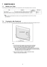
Страница 23: ...23 13 Wipe the screen board surface Gently wipe the screen board surface with a soft moist cloth ...
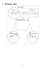
Страница 28: ...28 5 SECTIONAL VIEW ...
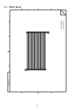
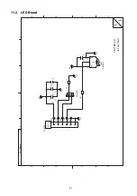
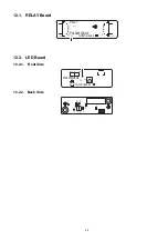
Страница 48: ...48 12 CIRCUIT BOARDS Index 12 1 RELAY Board 12 2 LED Board ...
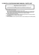
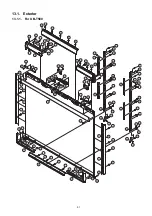
Страница 50: ...50 13 PARTS LOCATION AND MECHANICAL PARTS LIST ...
Страница 53: ...53 13 1 2 For UB T580W To be continued later ...
Страница 56: ...56 13 2 2 For UB T580W To be continued later ...
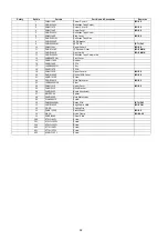
Страница 57: ...57 14 REPLACEMENT PARTS LIST ...


