49
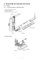
6.6.1.
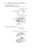
CONTROL Board, PANEL Board, and POWER Board
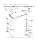
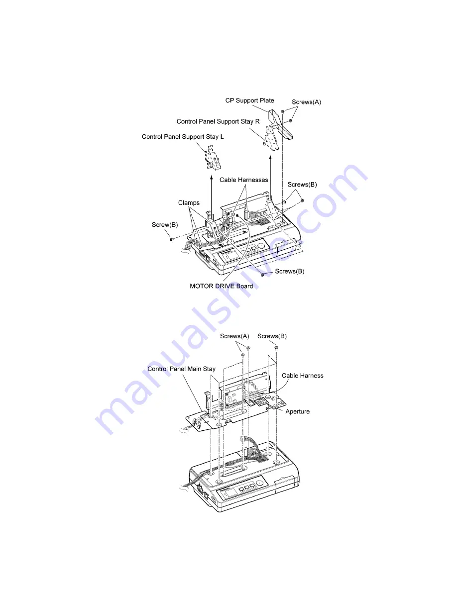
1. Remove the 2 cable harnesses from the MOTOR DRIVE Board.
2. Release the cable from the 3 clamps.
3. Remove the 2 screws (A) and then remove the CP Support Plate.
4. Remove the 6 screws. Then remove the Control Panel Support Stays (R and L) on both sides.
5. Remove the 3 screws (A) and 4 screws (B).
Then remove the Control Panel Main Stay while pulling the cable from the aperture.
Содержание UB-5338C
Страница 9: ...9 2 3 External View ...
Страница 10: ...10 2 4 Control Panel Operation ...
Страница 11: ...11 2 5 External Dimensions 2 5 1 UB 5838C ...
Страница 12: ...12 2 5 2 UB 5338C ...
Страница 101: ...101 13 Exploded View and Replacement Parts List ...
Страница 102: ...102 13 1 Framework of Projected Diagram ...
Страница 103: ...103 13 2 Cabinet Unit ...
Страница 105: ...105 13 3 Motor Drive Unit Sensor Unit ...
Страница 107: ...107 13 4 Control Box Unit ...
Страница 109: ...109 13 5 Screen Feed Roller Unit ...
Страница 111: ...111 13 6 Scanner Unit ...
Страница 113: ...113 13 7 Panel Unit ...
Страница 115: ...115 13 8 Frame Unit ...
Страница 117: ...117 13 9 Rear Cover Unit ...
Страница 119: ...119 13 10 Packing ...

