6
- 27
2WAY SYSTEM
Trouble Diagnosis
6
4. 2WAY Alarm Codes
P14 Alarm
Alarm code
Alarm meaning
Alarm conditions
Probable cause
Check and
Correction
Example
Notes
P14
O
2
sensor operation
(1)
1-1
System configuration
Is an O
2
sensor being used?
If “Yes”, see “3-1”.
If “No”, see “2-1”.
If “Yes”, change the setting of item code 0B to
“0000” from “0001”.
If “No”, see “3-1”.
If “Yes”, see “3-3”.
If “No”, see “3-2”.
(2)
2-1
Indoor EEPROM setting
Is the EEPROM setting, item code 0B, on the indoor control board set to 0001?
(3)Indoor control board
3-1
3-2
3-3
Is the alarm triggered if the EXCT socket (wire) is disconnected, and the power is reset?
Since there is no error, see what happens.
Indoor control board defective
replace board
—
—
(1)
2
Alarm Generated”
from the indoor unit.
(2)
It is judged an error whenever the outdoor unit receives the signal “O
With the indoor unit's EEPROM setting (item code 0B) set to 0001, the EXCT input was
shorted.
—
P16 Alarm
2WAY SYSTEM
Trouble Diagnosis
4. 2WAY Alarm Codes
Alarm code
Alarm meaning
Alarm conditions
Probable cause
Check
Correction
Example
Notes
P16
Compressor 1 (INV) overcurrent alarm
This alarm occurs when current trouble or current detection
trouble occur (when trouble judgement current is detected
in the secondary current).
*
When more than the current values shown in the table are
instantly detected in the secondary current.
Changed to output error by current regardless of the inverter
frequency.
There is a strong possibility of a compressor failure.
An alarm occurs for current detection trouble when it is judged that no current is flowing after
start (DCCT is damaged). In this case, the cause is a DCCT failure.
Check the power wiring and connector wiring.
It is possible to resolve this trouble by limiting the maximum frequency.
—
—
Inverter compressor
HIC PCB
U
V
W
Secondary
current
Horsepower of unit
Secondary current
Current (A)
8HP
19.6
10HP
21.8
12HP
17.6
14HP
21.0
16HP
22.5
18HP
21.0
20HP
21.0
P22 Alarm
Alarm code
Alarm meaning
Alarm conditions
Probable cause
P22
Fan motor trouble
Fan motor start failure, fan motor Hall IC input failure
Possible causes are a Hall IC input circuit failure and a fan HIC failure.
Check
Check the fan motor wiring, the Hall IC wiring, and the connector connections.
If the wiring and connectors are normal, then check that the capacitor of the Hall IC input circuit
is securely soldered on the outdoor unit control PCB. Also use a tester and measure the
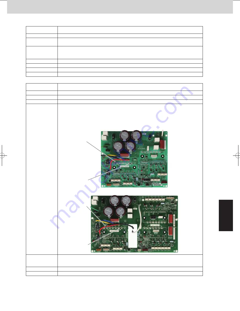
resistance between fan HIC power (HIC+) and ground (HIC–).
If there is a short-circuit, there is an HIC malfunction.
Correction
(1) If there is a fan HIC failure or circuit failure, replace the PCB.
(2) If the fan motor is locked, replace the fan motor.
Example
Notes
If the fan does not start, the below corrections may be effective.
—
Turn OFF the power, and check the continuity of “+” and “–” on the fan circuit PCB.
P20 Alarm
Alarm code
P20
Alarm meaning
Alarm conditions
Probable cause
Check
Correction
Example
Notes
High load alarm
The high pressure increase is not rapid but the alarm occurs when the horsepower down does
not meet the anticipated time.
(1) Forgot to open the valve.
(2) Operation failure of mechanical valve
(3) Idle away of outdoor fan
Check the valve, mechanical valve and outdoor fan.
—
—
—
HIC PCB for 8HP to 16HP
(A747038)
HIC PCB for 18HP and 20HP
(A747036)
HIC +
(P)
HIC -
(NV)
HIC +
(P)
HIC -
(NV)
SM830204-05_2WAY SYS.indb 27
2015/01/20 17:45:22
Содержание U-20ME1E81
Страница 54: ... MEMO 1 46 ...
Страница 102: ... MEMO 3 36 ...
Страница 116: ... MEMO 4 14 ...
Страница 177: ...201502 ...


