10
3
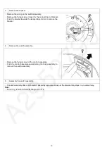
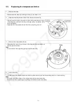
Remove the bracket
• Remove the wiring on the switch assembly.
• Remove the fixing screws (2 pcs) for the connecting rod bracket.
• Push the bracket towards the temperature limiter, to remove the
bracket.
4
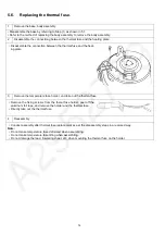
Remove the switch assembly.
• Remove the fixing screws of the control baseplate.
• Push the control baseplate upward along the body assembly, to
remove the switch assembly.
5
Assembly the switch assembly.
• Conduct assembly after control switch assembly replacement as per the disassembly steps in a reversed way.
Note:
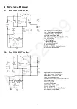
• For wiring, refer to Schematic Diagram on P. 4.
Содержание SR-JP185WVA-US
Страница 4: ...4 2 Schematic Diagram 2 1 For 120V 650W model 2 2 For 220V 400W model ...
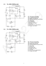
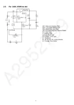
Страница 5: ...5 2 3 For 220V 650W model 2 4 For 230V 650W model ...
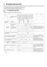
Страница 6: ...6 2 5 For 240V 650W model ...
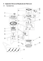
Страница 15: ...15 6 Exploded View and Replacement Parts List 6 1 Exploded View ...
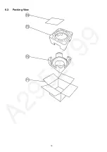
Страница 16: ...16 6 2 Packing View ...

