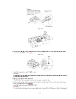
the optical pickup.
7. Press “3” on the remote control transmitter.
“ROM LASER” will be displayed to indicate the ROM data confirmation mode.
8. Confirm that the reading of the laser power meter is within the specified range.
Specified range (ROM data laser power): / 540
µµµµ
W ~ 660
µµµµ
W
9. Press “1” on the remote control transmitter.
“RAM LASER” will be displayed to indicate the RAM data confirmation mode.
10. Confirm that the reading of the laser power meter is within the specified range.
Specified range (RAM data laser power): / 540
µµµµ
W ~ 660
µµµµ
W
If the reading in either step 8 or 10 above is not within the specified range, first switch off the power, and then
reset the unit to the adjustment mode and repeat the adjustment procedure.
11. Turn the power OFF.
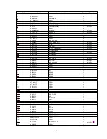
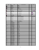
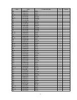
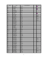
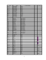
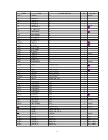
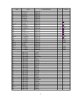
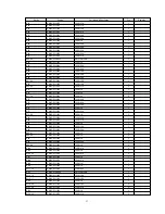
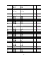
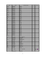
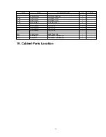
18. Replacement Parts List
Notes:
- Important safety notice:
Components identified by
mark have special characteristics important for safety.
Furthermore, special parts which have purposes of fire-retardant (resistors), high-quality sound (capacitors), low-noise
(resistors), etc. are used.
When replacing any of components, be sure to use only manufactures specified parts shown in the parts list.
- The <IA> <IB> <IC> <ID> marks in Remarks indicate language of instruction manual.
<IA> : English, Spanish, Swedish, Russian, Czech, Polish
<IB> : English
<IC> : German, Italian, French
<ID> : Netherlands, Danish
- The parenthesized indications in the Remarks columns specify the areas. (Refer to the cover page for area.)
- The marking <MAVD> indicates in Remarks colums parts that are supplied by MAVD.
- The marking [RTL] indicates that Retention Time is Limited for this item. After the discontinuation of this assembly in
production, the item will continue to be available for a specific period of time. The retention period of availability is
dependent on the type of assembly, and in accordance with the laws governing part and product retention. After the end
of this period, the assembly will no longer be available.
- All parts are supplied by MESA.
44
Содержание SJ-MD150
Страница 5: ...4 Caution for AC Mains Lead 5 ...
Страница 10: ...10 ...
Страница 15: ...15 ...
Страница 16: ...16 ...
Страница 17: ... Check the MD servo P C B B side as shown below 17 ...
Страница 18: ...8 6 Replacement for the magnetic head and optical pickup Follow the Step 1 Step 3 of item 8 1 18 ...
Страница 19: ...19 ...
Страница 20: ...20 ...
Страница 21: ...21 ...
Страница 22: ...8 7 Replacement for the belt and loading motor Follow the Step 1 Step 3 of item 8 1 22 ...
Страница 23: ...23 ...
Страница 25: ...25 ...
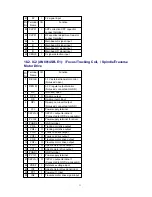
Страница 36: ...30 TEST02 Test terminal Not used open 36 ...
Страница 48: ...48 ...
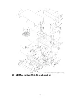
Страница 57: ...20 MD Mechanism Unit Parts Location 57 ...
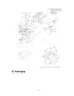
Страница 58: ...21 Packaging 58 ...
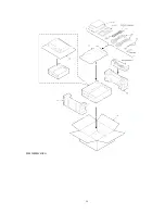
Страница 59: ...F000300000YM KH 59 ...


