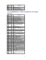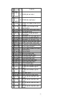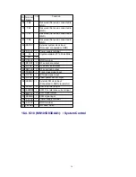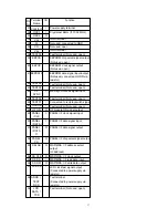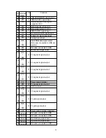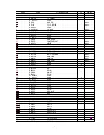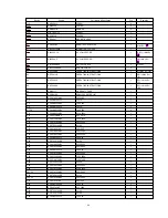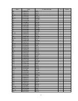
Pin
No.
Terminal
Name
I/O
Function
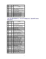
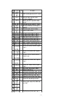
95 P102/AN2 -
Not used, connected to GND
96 P101/AN1 -
Not used, connected to GND
97
AV
SS
-
GND terminal
98 P100/AN0 -
Not used, connected to GND
99
VREF
I
Reference voltage input
100 AV
CC
I
Power supply terminal
17. Measurements and Adjustments
Note:
Because this unit uses the optical magnetic recording, the unit outputs over 10 times more laser than a CD player
does. In adjustment mode, the laser is always being output. Therefore, be especially careful not to look laser
beam directly or to touch the laser beam when adjusting the unit and checking its operation.
17.1. Necessary instruments
- Laser power meter (LE8010)
- Test disc (Pre-mastered disc RFKV0006 or RFKV0014)
- Recordable disc available on sales route / (with music recorded)
- Insulated driver for adjustment such as a ceramic driver
- Extension cable kit (RFKZJMD100EK)
- Remote control transmitter
17.2. Set to the unit to adjustment mode
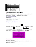
1. Turn the power ON.
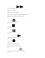
2. With no MD loaded in the unit, press and hold the STOP button (
) for at least 2 seconds. And then while still
pressing the STOP button (
), press the F.SEARCH button (
) for at least 2
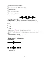
seconds. The unit is set to the self-diagnostic function and is displayed “MD TEST”. Refer to
Fig. 17-1.
Fig. 17-1.
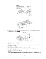
Caution on optical pickup:
- The optical pickup and the magnetic head are structured precisely; therefore, they are very fragile. Be careful not to touch
them with the edge of laser power meter.
- The sensor of the laser power meter is a very fine part. Be careful not to touch it to the optical pickup lens.
- The focus point of the laser reaches to 180°C. Therefore, avoid using laser power for a long time because the sensor of
the laser power meter may be burned.
41
Содержание SJ-MD150
Страница 5: ...4 Caution for AC Mains Lead 5 ...
Страница 10: ...10 ...
Страница 15: ...15 ...
Страница 16: ...16 ...
Страница 17: ... Check the MD servo P C B B side as shown below 17 ...
Страница 18: ...8 6 Replacement for the magnetic head and optical pickup Follow the Step 1 Step 3 of item 8 1 18 ...
Страница 19: ...19 ...
Страница 20: ...20 ...
Страница 21: ...21 ...
Страница 22: ...8 7 Replacement for the belt and loading motor Follow the Step 1 Step 3 of item 8 1 22 ...
Страница 23: ...23 ...
Страница 25: ...25 ...
Страница 36: ...30 TEST02 Test terminal Not used open 36 ...
Страница 48: ...48 ...
Страница 57: ...20 MD Mechanism Unit Parts Location 57 ...
Страница 58: ...21 Packaging 58 ...
Страница 59: ...F000300000YM KH 59 ...

