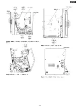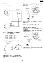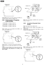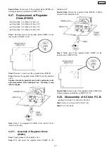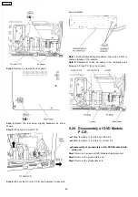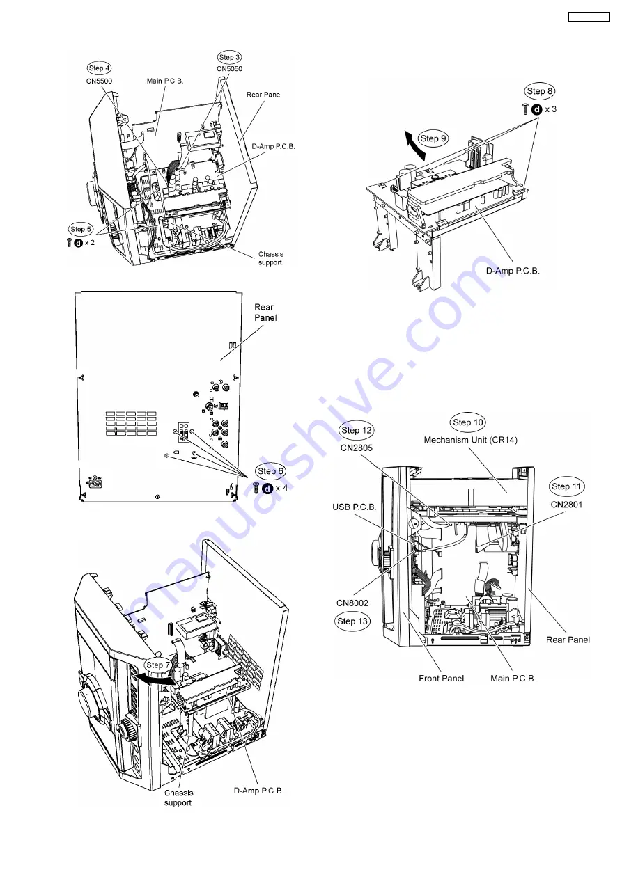
Step 6 Remove 4 screws at the rear panel.
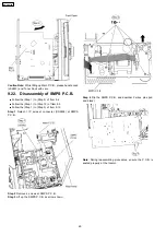
Step 7 Lift up the D-Amp P.C.B. together with the classic
support as arrow shown.
Step 8 Remove 3 screws from D-Amp P.C.B..
Step 9 Lift up D-Amp P.C.B. as arrow shown.
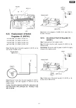
Step 10 Position Mechanism unit (CR14) according to the
diagram show.
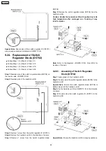
Step 11 Connect 50P FFC cable at the connector (CN2801) on
Main P.C.B..
Step 12 Connect 11P FFC cable at the connector (CN2805) on
Main P.C.B..
Step 13 Connect 5P cable at the connector (CN8002) on USB
P.C.B..
Step 14 Attach original cable with extension cable (REXX0683)
(8P cable from H5801 to CN5500).
Step 15 Connect extension cable (REEX0930) (17P cable from
CN2808 to CN5050).
73
SA-VK470EE
Содержание SA-VK470EE
Страница 3: ...3 SA VK470EE ...
Страница 12: ...12 SA VK470EE ...
Страница 40: ...40 SA VK470EE ...
Страница 42: ...9 3 Main Components and P C B Location 42 SA VK470EE ...
Страница 54: ...9 15 2 Replacement of Motor Capstan Belt A Capstan Belt B and Winding Belt 54 SA VK470EE ...
Страница 88: ...SA VK470EE 88 ...
Страница 98: ...98 SA VK470EE ...
Страница 116: ...SA VK470EE 116 ...
Страница 124: ...SA VK470EE 124 ...
Страница 136: ...136 SA VK470EE ...
Страница 137: ...24 Exploded Views 24 1 Cabinet Parts Location SA VK470EE 137 ...
Страница 138: ...SA VK470EE 138 ...
Страница 139: ...24 2 Deck Mechanism Parts Location RAA4111 S SA VK470EE 139 ...
Страница 140: ...24 3 Packaging SA VK470EE 140 ...

