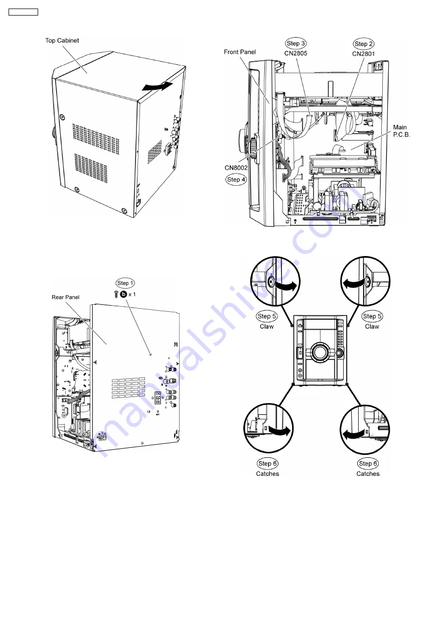
9.5. Disassembly of Mechanism
Unit (CR14)
•
•
•
•
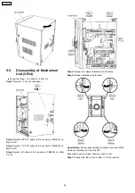
Follow the (Step 1) to (Step 5) of Item 9.4
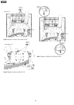
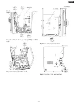
Step 1 Remove 1 screw at rear panel.
Step 2 Detach 50P FFC cable at the connector (CN2801) on
Main P.C.B..
Step 3 Detach 11P FFC cable at the connector (CN2805) on
Main P.C.B..
Step 4 Detach 5P cable at the connector (CN8002) on USB
P.C.B..
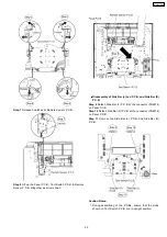
Step 5 Release the claws outwards on both sides.
Step 6 Release catches at both sides.
Special Note: During reassembling procedure, ensure both the
claws and catches are fully catched.
Assembly is secured upon hearing a click sound.
Step 7 Release the tabs at the bottom of the front panel.
44
SA-VK470EE
Содержание SA-VK470EE
Страница 3: ...3 SA VK470EE ...
Страница 12: ...12 SA VK470EE ...
Страница 40: ...40 SA VK470EE ...
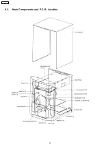
Страница 42: ...9 3 Main Components and P C B Location 42 SA VK470EE ...
Страница 54: ...9 15 2 Replacement of Motor Capstan Belt A Capstan Belt B and Winding Belt 54 SA VK470EE ...
Страница 88: ...SA VK470EE 88 ...
Страница 98: ...98 SA VK470EE ...
Страница 116: ...SA VK470EE 116 ...
Страница 124: ...SA VK470EE 124 ...
Страница 136: ...136 SA VK470EE ...
Страница 137: ...24 Exploded Views 24 1 Cabinet Parts Location SA VK470EE 137 ...
Страница 138: ...SA VK470EE 138 ...
Страница 139: ...24 2 Deck Mechanism Parts Location RAA4111 S SA VK470EE 139 ...
Страница 140: ...24 3 Packaging SA VK470EE 140 ...

