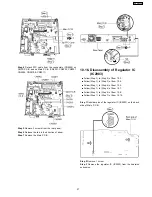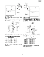
Step 4 Detach FFC cable from the connectors (CN5802) on
SMPS P.C.B. and on Main P.C.B. (CN2001, CN2003, CN2007,
CN2009, CN2010 & CN2011)
Step 5 Remove 3 screws from the rear panel.
Step 6 Release the tab in the direction of arrow.
Step 7 Remove the Main P.C.B.
10.16. Disassembly of Regulator IC
(IC2903)
•
•
•
•
Follow (Step 1) to (Step 3) of Item 10.3.
•
•
•
•
Follow (Step 1) to (Step 3) of Item 10.4.
•
•
•
•
Follow (Step 1) to (Step 4) of Item 10.5.
•
•
•
•
Follow (Step 1) to (Step 4) of Item 10.7.
•
•
•
•
Follow (Step 1) to (Step 4) of Item 10.8.
•
•
•
•
Follow (Step 1) to (Step 7) of Item 10.15.
Step 1 Desolder pins of the regulator IC (IC2903) on the back
side of Main P.C.B.
Step 2 Remove 1 screw.
Step 3 Remove the regulator IC (IC2903) from the heatsink
extrussion.
57
SA-PT750PL
Содержание SA-PT750PL
Страница 11: ...11 SA PT750PL ...
Страница 17: ...7 5 Using the Music Port 28 17 SA PT750PL ...
Страница 20: ...8 New Features 8 1 About HDMI 8 1 1 What is HDMI 8 1 2 Advanced Digital Pictures 20 SA PT750PL ...
Страница 21: ...8 1 3 Advanced Digital Sound 8 1 4 Easy to Use 8 1 5 HDMI Compatible Products 21 SA PT750PL ...
Страница 50: ...10 2 Main Components and P C B Locations 50 SA PT750PL ...
Страница 67: ...67 SA PT750PL ...
Страница 84: ...SA PT750PL 84 ...
Страница 86: ...SA PT750PL 84 ...
Страница 94: ...SA PT750PL 92 ...
Страница 96: ...94 SA PT750PL ...
Страница 114: ...SA PT750PL 112 ...
Страница 127: ...25 Exploded Views 125 SA PT750PL ...
Страница 128: ...126 SA PT750PL ...
Страница 129: ...25 1 Cabinet Parts Location SA PT750PL 127 ...
Страница 130: ...SA PT750PL 128 ...
Страница 131: ...25 2 Packaging SA PT750PL 129 ...


