careful not to touch them with the edge of the laser
power meter.
•
The sensor of the laser power meter is a very fine part.
Be careful not to touch it to the optical pickup lens.
•
The focus point of the laser reaches to 356°F.
Therefore, avoid adjusting using laser power for a long
time because the sensor of the laser power meter may
be burned.
•
Do not allow the write power to even momentarily reach
or exceed 7.5 mW. Doing so will result in damage to the
optical pickup.
•
Do not set the unit to the laser power adjustment mode
with the MD loaded. Doing so may result in damage to
the MD.
10.4.3. Adjustment Procedure
1. Enter “1” using numeric pad on the remote control with no
MD loaded.
→
FL display “Rough ADJ”.
(Read power adjustment mode)
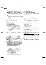
2. Slide sensor cover on the laser power meter. (Fig. 1)
3. Place the sensor on the laser power meter right on top of
the optical pickup. (Fig. 2)
4. Confirm that the reading of the laser power meter is within
the standard value. If the value is out of the range, adjust
VR1. (Fig. 3)
Standard value (read power) : 600µW
Cautions
Proceeding on to the subsequent adjustment procedure
with the read power exceeding 650µW will result in
damage to the optical pickup.
5. Press “MEMORY/ENTER” button on the unit.
→
FL display “ROUGH ADJ.OK” flash for 3 times and
display the next indication.
→
FL display “FINE ADJ”
(Write power adjustment mode)
6. Adjust VR1 until reading of the laser power meter is within
the standard value. (Fig. 3)
Standard value (write power) : 6.8mW ± 0.1mW
Cautions
Do not allow the write power to reach or exceed 7.5mW,
even for a moment. Doing so will result in damage to the
optical pickup.
7. Press “MEMORY/ENTER” button on the unit.
→
FL display “FINE ADJ.OK” flash for 3 times and display
the next indication.
→
FL display “ROM-D.CHECK”
(ROM data check mode)
8. Confirm that the reading of the laser power meter is within
the standard value.
Standard value(ROM data laser power) : 320µW~380µ
9. Press “MEMORY/ENTER” button on the unit.
→
FL display “RAM-D.CHECK”
(RAM data check mode)
10. Confirm that the reading of the laser power meter is within
the standard value.
Standard value(RAM data laser power) : 620µW~740µ
11. Press “EJECT” to cancel adjustment mode, then press
“POWER” button to turn off the power.
Note : If the value in step 8 and step 10 is out of standard
value, turn off the power and readjust from the beginning.
Caution
Upon completion of adjustment, make sure to perform reset
operation.
24
SA-PM30MD
or lower
Standard value (write power) : 4.8 mW +/- 0.1mW
Standard value(ROM data laser power):540-660uW
540-660uW
5.5mW
5.5 mW. Doing so will result in damage to the
Содержание SA-PM30MD
Страница 6: ...6 Caution for AC Mains Lead 6 SA PM30MD ...
Страница 7: ...7 Operation Procedures 7 SA PM30MD ...
Страница 8: ...8 SA PM30MD ...
Страница 74: ...16 Wiring Connection Diagram 74 SA PM30MD ...
Страница 75: ...17 Troubleshooting Guide 75 SA PM30MD ...
Страница 76: ...76 SA PM30MD ...
Страница 77: ...77 SA PM30MD ...
Страница 78: ...78 SA PM30MD ...
Страница 79: ...79 SA PM30MD ...
Страница 80: ...80 SA PM30MD ...
Страница 81: ...81 SA PM30MD ...
Страница 82: ...82 SA PM30MD ...
Страница 84: ...18 1 1 Deck Mechanism Parts Location 18 1 Deck Mechanism RAA4106 84 SA PM30MD ...
Страница 86: ...18 2 MD Mechanism 18 2 1 MD Mechanism Parts location 86 SA PM30MD ...
Страница 88: ...18 3 CD Loading Mechanism 18 3 1 CD Loading Mechanism Parts Location 88 SA PM30MD ...
Страница 90: ...18 4 1 Cabinet Parts Location 18 4 Cabinet 90 SA PM30MD ...
Страница 91: ...91 SA PM30MD ...

