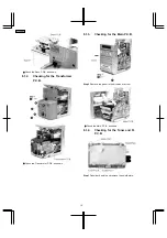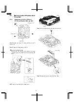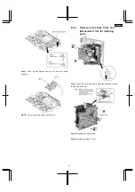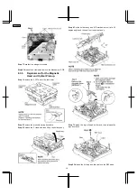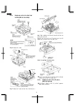
Step 2 Desolder 6 points and remove the shield plate.
•
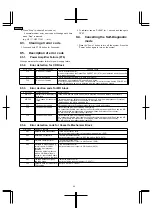
Check the Tuner and FL P.C.B. as shown.
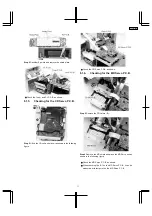
8.1.5. Checking for the CD Servo P.C.B.
Step 2 Lift up the CD unit and place it as shown in the following
figure.
•
Check the CD Servo P.C.B. as shown.
8.1.6. Checking for the MD Servo P.C.B.
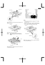
Step 2 Remove the CD fixture (B).
Step 4 Remove the MD shield and place the MD Servo unit as
shown in the following figure.
•
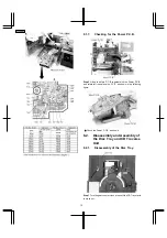
Check the MD Servo P.C.B. as shown.
•
When checking the IC1 on the MD Servo P.C.B., it can be
measured with test point on the MD Servo P.C.B.
11
SA-PM30MD
Содержание SA-PM30MD
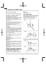
Страница 6: ...6 Caution for AC Mains Lead 6 SA PM30MD ...
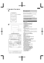
Страница 7: ...7 Operation Procedures 7 SA PM30MD ...
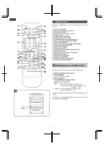
Страница 8: ...8 SA PM30MD ...
Страница 74: ...16 Wiring Connection Diagram 74 SA PM30MD ...
Страница 75: ...17 Troubleshooting Guide 75 SA PM30MD ...
Страница 76: ...76 SA PM30MD ...
Страница 77: ...77 SA PM30MD ...
Страница 78: ...78 SA PM30MD ...
Страница 79: ...79 SA PM30MD ...
Страница 80: ...80 SA PM30MD ...
Страница 81: ...81 SA PM30MD ...
Страница 82: ...82 SA PM30MD ...
Страница 84: ...18 1 1 Deck Mechanism Parts Location 18 1 Deck Mechanism RAA4106 84 SA PM30MD ...
Страница 86: ...18 2 MD Mechanism 18 2 1 MD Mechanism Parts location 86 SA PM30MD ...
Страница 88: ...18 3 CD Loading Mechanism 18 3 1 CD Loading Mechanism Parts Location 88 SA PM30MD ...
Страница 90: ...18 4 1 Cabinet Parts Location 18 4 Cabinet 90 SA PM30MD ...
Страница 91: ...91 SA PM30MD ...


