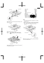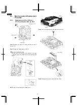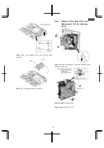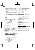
Step 7 Desolder the plunger terminals.
Step 8 Release the 4 claws and remove the Mechanism P.C.B.
8.3.3. Replacement for the Magnetic
Head and Optical Pick-up.
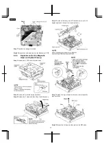
Step 1 Remove the 2 FFCs from the connector.
Step 2 Remove the pressure spring from latch.
Step 3 Release the 2 claws and then lift up the holder ass’y.
Step 4 Set the holder ass’y and MD mechanism unit at a 60
degree angle and then pull out the holder ass’y.
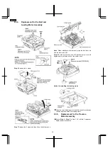
Step 7 Spread the lugs of head shifter and then release the
lugs from boss.
Step 9 Release the 2 claws and then remove the REF base.
16
SA-PM30MD
Содержание SA-PM30MD
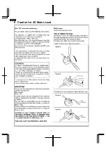
Страница 6: ...6 Caution for AC Mains Lead 6 SA PM30MD ...
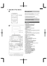
Страница 7: ...7 Operation Procedures 7 SA PM30MD ...
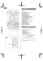
Страница 8: ...8 SA PM30MD ...
Страница 74: ...16 Wiring Connection Diagram 74 SA PM30MD ...
Страница 75: ...17 Troubleshooting Guide 75 SA PM30MD ...
Страница 76: ...76 SA PM30MD ...
Страница 77: ...77 SA PM30MD ...
Страница 78: ...78 SA PM30MD ...
Страница 79: ...79 SA PM30MD ...
Страница 80: ...80 SA PM30MD ...
Страница 81: ...81 SA PM30MD ...
Страница 82: ...82 SA PM30MD ...
Страница 84: ...18 1 1 Deck Mechanism Parts Location 18 1 Deck Mechanism RAA4106 84 SA PM30MD ...
Страница 86: ...18 2 MD Mechanism 18 2 1 MD Mechanism Parts location 86 SA PM30MD ...
Страница 88: ...18 3 CD Loading Mechanism 18 3 1 CD Loading Mechanism Parts Location 88 SA PM30MD ...
Страница 90: ...18 4 1 Cabinet Parts Location 18 4 Cabinet 90 SA PM30MD ...
Страница 91: ...91 SA PM30MD ...

