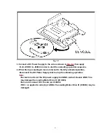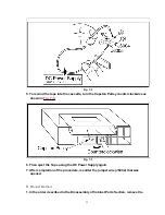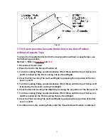
3. Connect the AC Cord.
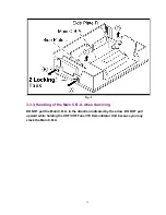
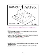
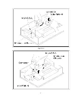
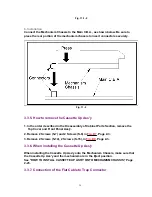
4. The VCR turns ON automatically and the Cassette Holder Unit is loaded. The top of
Set Lever L and R is locked by the First Locking Tab (Left and Right). Then the
VCR turns OFF.
5. Clear the First Locking Tab (Left and Right) by pressing the (a) portion of the Set
Lever L and R.
6. Turn ON the Power Switch.
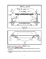
7. The top of Set Lever R is locked by the Second Locking Tab (Same as Step 4).
8. Clear the Second Locking Tab ( Right) by pressing the (a) portion of the Set Lever
R.
9. Turn ON the Power Switch.
10. The top of Set Lever L and R is locked by the Third Locking Tab (Same as Step 4).
11. Clear the Third Locking Tab (Left and Right) by pressing the (a) portion of the Set
Lever L and R.
12. Turn ON the Power Switch.
13. The Cassette Holder Unit is in the down position and the loading operation is
completed.
3.3.10. Black Screws on the Chassis
Black Screws are used on the Mechanism Chassis to identify screws that require
adjustment.
3.3.11. Variable Voltage Isolation Transformer
Because a Hot Chassis Ground is present in the Switched Mode Power Supply
Circuit, an Isolation Transformer must be used. Also, in order to have the ability to
increase the input voltage slowly, when troubleshooting this type of Power Supply
Circuit, a variable isolation transformer is required.
3.3.12. Cylinder Rotation in STOP mode
The cylinder will continue to rotate for approximately 5 minutes after the STOP button
is pressed in Play mode etc. Eject the tape in order to stop the cylinder.
3.3.13. Service of UHF/VHF TUNER/TV DEMODULATOR UNIT
Since the UHF/VHF TUNER/TV DEMODULATOR UNIT has already been pre-adjusted
at the factory, do not try to adjust the UHF/VHF TUNER/TV DEMODULATOR UNIT.
The UHF/VHF TUNER/TV DEMODULATOR UNIT replacement part is available as a
complete assembly unit only.
3.3.14. Supply Unit for Infrared Remote Control Unit
35
Содержание PV-4601 A
Страница 14: ...Fig 2 3 14 ...
Страница 27: ...Fig 11 1 1 27 ...
Страница 40: ...Fig D1 40 ...
Страница 42: ...Fig D2 42 ...
Страница 43: ...Fig D3 43 ...
Страница 44: ...Fig D4 44 ...
Страница 45: ...Fig D5 45 ...
Страница 46: ...Fig D7 46 ...
Страница 47: ...Fig D8 47 ...
Страница 51: ...Fig M2 1 Fig M2 2 51 ...
Страница 53: ...Fig M4 1 53 ...
Страница 77: ...Fig M19 77 ...
Страница 84: ...Fig J5 84 ...
Страница 85: ...Fig J6 85 ...
Страница 87: ...Fig J9 87 ...
Страница 88: ...Fig J10 88 ...
Страница 89: ...Fig J11 89 ...
Страница 90: ...Fig J12 90 ...
Страница 91: ...Fig J13 91 ...
Страница 92: ...Fig J15 92 ...
Страница 93: ...93 ...
Страница 96: ...96 ...
Страница 102: ...with the holes on the Pinch Lift Cam as shown in Fig A6 102 ...
Страница 103: ...103 ...
Страница 105: ...Fig K1 105 ...
Страница 106: ...Fig K2 106 ...
Страница 107: ...Fig K3 107 ...
Страница 109: ...Fig B1 109 ...
Страница 114: ...Fig E1 4 3 2 HOW TO READ THE ADJUSTMENT PROCEDURES 114 ...
Страница 115: ...Fig E2 115 ...
Страница 134: ...R6004 ERJ6GEYJ333V MGF CHIP 1 10W 33K 134 ...
Страница 136: ...R6085 ERJ6GEYJ223V MGF CHIP 1 10W 22K 136 ...
Страница 140: ...C4601 ECEA1CKA100 ELECTROLYTIC 16V 10 140 ...
Страница 147: ...R6065 ERJ6GEYJ223V MGF CHIP 1 10W 22K 147 ...
Страница 167: ...9 11 Operation Block Diagrams 1 167 ...
Страница 178: ......
Страница 204: ......
Страница 205: ......

