REC 1 2 : 0 0AM
CH0 8
0 : 0 0 : 0 0
SLP
0 : 25
STEREO
SAP
MONO
Warning and Instruction Displays
These displays will alert you to a missed operation or
provide further instructions.
On Screen Displays (OSD)
Function & Channel Display
Whenever a function button
is pushed (PLAY, FF, etc.)
or the channel is changed,
a 4 second OSD will
appear first in large and
then small characters.
If no active channels are
found for CHANNEL
MEMORY...
2
Push MENU to display t
he
menu.
Rotate and push the wheel
to make your selection.
Menu Screen
PLEASE CHECK ANTENNA
CABLE CONNECTION THEN
PUSH VCR CH UP KEY AGAIN
NO CH FOUND
Push DISPLAY to display and remove the
overlay shown below.
FF
MENU
SELECT : ROTATE WHEEL
SET : PUSH WHEEL
END : PUSH MENU KEY
SET UP VCR
SET C LOCK
SET UP CHANNEL
I D I OMA / LANGUE : ENGL I SH
TO CANCEL TIMER REC
PUSH POWER THEN STOP KEY
NO CASSETTE
PLEASE INSERT A CASSETTE
If you push PLAY, FF, REW,
or REC on the remote control
or if you push REC and
PLAY, PLAY, FF, REW, or
REC on the VCR without a
cassette inserted...
CHECK CASSETTE
RECORD TAB
If you push REC on the
remote control or REC
and PLAY on the VCR,
and a cassette is inserted
with no record tab...
TURN VCR OFF
FOR TIMER RECORDING
After a Timer Program has
been set...
PLEASE SET CLOCK
BEFORE PROGRAMMING
If you attempt to set or
review a Timer Recording
and the Clock is not set...
PROGRAM IS INCOMPLETE
If a Timer Program was not
completed before exiting
the Program mode...
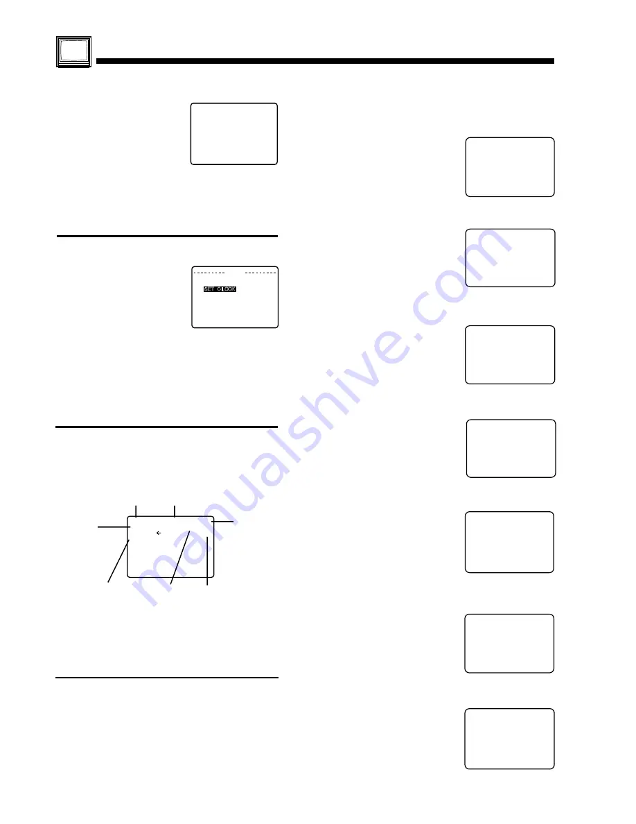
Rec Time
Remaining
Counter
Tape Speed
Channel
Function Status
Time
• To get the most from each feature, it is
recommended that you read the Operation
Manual before attempting any operation.
If a blank section of tape is encountered in the Play
mode or the channel you select has no broadcast,
the TV screen will change to a solid blue field.
The screen will remain blue until a recorded signal
is again detected or an active channel is selected.
Blank Tape and will be Blue Screen
VCR Status & Clock Display
2
1
If you push POWER or
STOP during a Timer
Recording...
(visible in VCR mode only)
Receivable
Broadcast Types
Содержание PV-4601 A
Страница 14: ...Fig 2 3 14 ...
Страница 27: ...Fig 11 1 1 27 ...
Страница 40: ...Fig D1 40 ...
Страница 42: ...Fig D2 42 ...
Страница 43: ...Fig D3 43 ...
Страница 44: ...Fig D4 44 ...
Страница 45: ...Fig D5 45 ...
Страница 46: ...Fig D7 46 ...
Страница 47: ...Fig D8 47 ...
Страница 51: ...Fig M2 1 Fig M2 2 51 ...
Страница 53: ...Fig M4 1 53 ...
Страница 77: ...Fig M19 77 ...
Страница 84: ...Fig J5 84 ...
Страница 85: ...Fig J6 85 ...
Страница 87: ...Fig J9 87 ...
Страница 88: ...Fig J10 88 ...
Страница 89: ...Fig J11 89 ...
Страница 90: ...Fig J12 90 ...
Страница 91: ...Fig J13 91 ...
Страница 92: ...Fig J15 92 ...
Страница 93: ...93 ...
Страница 96: ...96 ...
Страница 102: ...with the holes on the Pinch Lift Cam as shown in Fig A6 102 ...
Страница 103: ...103 ...
Страница 105: ...Fig K1 105 ...
Страница 106: ...Fig K2 106 ...
Страница 107: ...Fig K3 107 ...
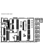
Страница 109: ...Fig B1 109 ...
Страница 114: ...Fig E1 4 3 2 HOW TO READ THE ADJUSTMENT PROCEDURES 114 ...
Страница 115: ...Fig E2 115 ...
Страница 134: ...R6004 ERJ6GEYJ333V MGF CHIP 1 10W 33K 134 ...
Страница 136: ...R6085 ERJ6GEYJ223V MGF CHIP 1 10W 22K 136 ...
Страница 140: ...C4601 ECEA1CKA100 ELECTROLYTIC 16V 10 140 ...
Страница 147: ...R6065 ERJ6GEYJ223V MGF CHIP 1 10W 22K 147 ...
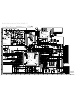
Страница 167: ...9 11 Operation Block Diagrams 1 167 ...
Страница 178: ......
Страница 204: ......
Страница 205: ......

