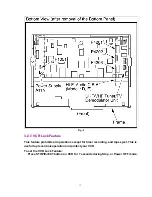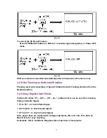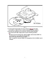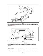
Fig. 1-5
Note:
When 1 to 4 listed in Lock code occurs, the VCR goes into VCR shut-off condition.
VCR stops and all VCR function buttons except for power become non-operational.
3.2.2. Service Position
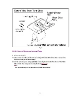
1. Service Position (1)
Service Position (1) is used for checking and replacing Mechanical and Electrical
parts.
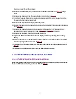
To position the VCR Unit for servicing as shown in
Fig. 2-1
, use the following
procedure.
1. In the order described in the Disassembly of Cabinet Parts Section, remove the
Top Cover, Power Supply Ass'y and Front Panel Ass'y .
2. Remove Screw (S-4) and Screw (S-5) in
Fig. D4
, Page 2-2.
3. Remove 2 Screws (S-6), 2 Screws (S-7), 2 Screws (S-8), Screw (S-9), Screw (S-10),
Screw (S-11), 2 Screws (S-12), and the Chassis Plate in
Fig. D7
, Page 2-3.
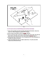
4. Remove the VCR Chassis Unit.
Refer to Note Item 5 and "How to remove the VCR Chassis Unit from the frame,"
Page 1-11.
5. Remove 2 Screws (S-13) in
Fig. D8
, Page 2-3.
6. Open the Mechanism Chassis and Cassette Up Ass'y.
7. Place the left side of the Cassette Up Ass'y on the front side of the Frame as shown
in
Fig. 2-1
.
8. Reinstall the Power Supply Ass'y as shown in
Fig. 2-1
, refer to Note Item 4.
9. Press VCR/TV button and CH down button together on VCR for over 5 seconds in
power off condition or Place a jumper between TP6001 and GND.
10
Содержание PV-4601 A
Страница 14: ...Fig 2 3 14 ...
Страница 27: ...Fig 11 1 1 27 ...
Страница 40: ...Fig D1 40 ...
Страница 42: ...Fig D2 42 ...
Страница 43: ...Fig D3 43 ...
Страница 44: ...Fig D4 44 ...
Страница 45: ...Fig D5 45 ...
Страница 46: ...Fig D7 46 ...
Страница 47: ...Fig D8 47 ...
Страница 51: ...Fig M2 1 Fig M2 2 51 ...
Страница 53: ...Fig M4 1 53 ...
Страница 77: ...Fig M19 77 ...
Страница 84: ...Fig J5 84 ...
Страница 85: ...Fig J6 85 ...
Страница 87: ...Fig J9 87 ...
Страница 88: ...Fig J10 88 ...
Страница 89: ...Fig J11 89 ...
Страница 90: ...Fig J12 90 ...
Страница 91: ...Fig J13 91 ...
Страница 92: ...Fig J15 92 ...
Страница 93: ...93 ...
Страница 96: ...96 ...
Страница 102: ...with the holes on the Pinch Lift Cam as shown in Fig A6 102 ...
Страница 103: ...103 ...
Страница 105: ...Fig K1 105 ...
Страница 106: ...Fig K2 106 ...
Страница 107: ...Fig K3 107 ...
Страница 109: ...Fig B1 109 ...
Страница 114: ...Fig E1 4 3 2 HOW TO READ THE ADJUSTMENT PROCEDURES 114 ...
Страница 115: ...Fig E2 115 ...
Страница 134: ...R6004 ERJ6GEYJ333V MGF CHIP 1 10W 33K 134 ...
Страница 136: ...R6085 ERJ6GEYJ223V MGF CHIP 1 10W 22K 136 ...
Страница 140: ...C4601 ECEA1CKA100 ELECTROLYTIC 16V 10 140 ...
Страница 147: ...R6065 ERJ6GEYJ223V MGF CHIP 1 10W 22K 147 ...
Страница 167: ...9 11 Operation Block Diagrams 1 167 ...
Страница 178: ......
Страница 204: ......
Страница 205: ......


