Chapter 6
Appendix — Technical information
ENGLISH - 205
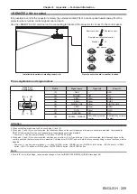
<SERIAL IN>/<SERIAL OUT> terminal
The <SERIAL IN>/<SERIAL OUT> terminal of the projector conforms with RS-232C so that the projector can be
connected to and controlled from a computer.
Connection
Single projector
Projector connecting terminals
Computer
D-Sub 9p (male)
Communication cable (straight)
D-Sub 9p (female)
D-Sub 9p (male)
Multiple projectors
D-Sub 9p (female)
D-Sub 9p (male)
Connecting terminals on projector 2
D-Sub 9p (female)
D-Sub 9p (male)
Connecting terminals on projector 1
Computer
D-Sub 9p (male)
D-Sub 9p (female)
D-Sub 9p (male)
Communication cable
Communication cable
When connecting using DIGITAL LINK compatible device
DIGITAL LINK compatible device
Computer
D-Sub 9p (female)
Projector connecting terminals
DIGITAL LINK
DIGITAL LINK
D-Sub 9p (male)
Communication cable (straight)
LAN cable (straight)
Note
f
The destination of [RS-232C] (
x
page 144) must be set according to the connection method.
f
When connecting using a DIGITAL LINK compatible device, set the [PROJECTOR SETUP] menu
→
[STANDBY MODE] (
x
page 138) to
[NORMAL] to control the projector during standby.
When [STANDBY MODE] is set to [ECO], the projector cannot be control during standby.
Pin assignments and signal names
D-Sub 9-pin (female)
Outside view
Pin No.
Signal name
Details
(1)
(5)
(6)
(9)
(1)
―
NC
(2)
TXD
Transmitted data
(3)
RXD
Received data
(4)
―
NC
(5)
GND
Earth
(6)
―
NC
(7)
CTS
Connected internally
(8)
RTS
(9)
―
NC


![NEC MT800[1].PART1 User Manual preview](http://thumbs.mh-extra.com/thumbs/nec/mt800-1-part1/mt800-1-part1_user-manual_250403-1.webp)


