background image

21

English 21

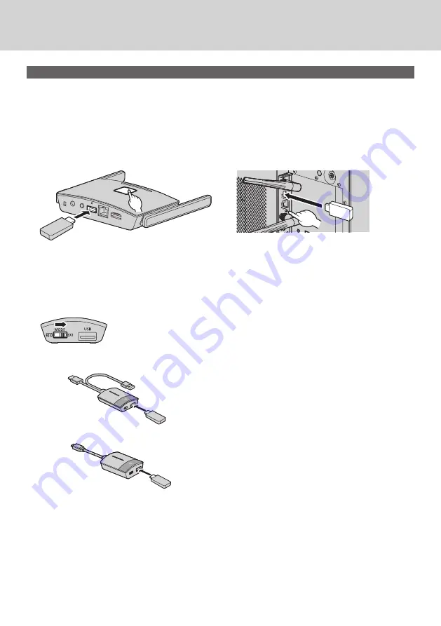
Pairing by saving a file to the USB memory

Supported device


Commercially available USB memory devices are supported. (Those with security functions are not supported.)


USB memory devices other than those formatted in FAT16 or FAT32 cannot be used.


Up to 32 GB of USB memory in size are supported.


Only single partition configuration is supported.


Be sure that the USB memory contains no files before using.

1

Connect the USB memory to the USB terminal of the receiver / receiver board.

1

2

Receiver

Receiver board

1

2

2

Press the FUNCTION button.

The LED lights up in white and the pairing file is saved to the USB memory.

Then, “Pairing OK” is displayed on the standby screen.

3

Remove the USB memory.

4

Slide the mode switch to the EXT side.

5

Supply power to the transmitter.

6

5

6

5

TY-WPB1/TY-WPB1W

TY-WPBC1/TY-WPBC1W

5 V/0.9 A

Power supply

5 V/0.9 A

Power supply

6

Connect the USB memory to the USB terminal of the transmitter.

7

Pairing is complete.

The main LED of the transmitter lights up in white.

8

Remove the USB memory from the transmitter.

Содержание PressIT TY-SB01WP

Страница 1: ...Transmitter Set TY WPBC1 TY WPBC1W WPS USB C Transmitter WPS is an abbreviation of Wireless Presentation System PressIT is a nickname for Wireless Presentation System English Thank you for purchasing the Panasonic product Please read these instructions before operating this product and retain them for future reference Be sure to read Safety Precautions page 2 to 3 before use This Operating Instruc...

Страница 2: ...the end Insufficient insertion may cause a fire due to an electric shock or heat generation Do not use the product with a damaged plug or loose outlet Do not damage the AC adaptor and power plug by damaging modifying forcibly bending twisting pulling or bundling them bringing them close to heat appliances placing heavy items on them etc INDEX Safety Precautions Safety Precautions 2 Before Using 4 ...

Страница 3: ...installation please ask a qualified technician or a dealer If installation is not carried out and secured correctly it can cause falling accidents If you terminate the use of the product ask a professional to remove it promptly Do not touch the bottom surface of the transmitter during use The bottom surface of the transmitter may be hot during and after use for a while resulting in a burn injury A...

Страница 4: ...me of the displayed contents on the application screen or Web setting screen may differ Precautions for use When transporting this product Do not apply excessive vibrations or impacts during transport Doing so may damage the internal parts resulting in a malfunction When installing this product Do not install the product outdoors This product is intended for exclusive use indoors Using it outdoors...

Страница 5: ...to remove dirt To remove stubborn dirt or fingerprints dampen a cloth with diluted neutral detergent 1 part detergent to 100 parts water wring out the cloth firmly and then wipe away the dirt Finally wipe away all the moisture with a dry cloth If water droplets get inside the unit operating problems may result Usage of a chemical cloth Follow the instructions for the chemical cloth Avoid contact w...

Страница 6: ...ns on the channels and frequencies at which you can use the wireless LAN Using receivers Up to 4 receivers can be installed for this product in the same room To ensure operations configure the settings in such a way that radio frequencies output from each receiver do not duplicate with each other Receivers installed in more than one rooms can be used by configuring the settings in the same way as ...

Страница 7: ...e content of e mail and personal information such as your ID password and or credit card numbers A malicious third party may access your personal or corporate network without authorization and engage in the following types of behaviour Retrieve personal and or secret information information leak Spread false information by impersonating a particular person spoofing Overwrite intercepted communicat...

Страница 8: ...WPS Transmitter TY WPB1 TY WPB1W WPS Transmitter TY WPB1 TY WPB1W 1 USB extension cable DPVF3513ZA X1 1 WPS USB C Transmitter Set TY WP2BC1 TY WP2BC1W WPS USB C Transmitter TY WPBC1 TY WPBC1W 2 Transmitter case TY WPC1 1 Conversion adaptor for pairing DPVF3516ZA X1 1 WPS USB C Transmitter TY WPBC1 TY WPBC1W WPS USB C Transmitter TY WPBC1 TY WPBC1W 1 Conversion adaptor for pairing DPVF3516ZA X1 1 W...

Страница 9: ...sed for 5 seconds or more while the power is being supplied Initialization will be complete in approx 1 minute 9 USB terminal Type A Connects the transmitter or USB memory when pairing devices Use this by connecting an HID device 10 LAN terminal RJ45 Connects to the network to change the settings of the product 11 HDMI output terminal Connects an imaging device equipped with HDMI input Receiver TY...

Страница 10: ...uct 4 USB terminal Type A Connects the transmitter or USB memory when pairing devices Use this by connecting an HID device mouse touch module page 9 5 FUNCTION LED Displays the pairing status 6 Power Indicator Displays the power supply status and connection statuses of LAN and USB 7 Reset button Restores the product to the factory default state Reset operation starts when the reset button is press...

Страница 11: ... when pairing see page 20 Set the switch to the STD side when receiving information from an HID device 6 USB terminal Type A Connects a USB memory when pairing with the receiver 7 USB terminal Type C Connect to an imaging device with a USB Type C terminal that supports DisplayPort Alt Mode output Transmitter TY WPB1 TY WPB1W USB C transmitter TY WPBC1 TY WPBC1W Transmitter case 2 transmitters and ...

Страница 12: ...t How to remove Press the button Remove the plug 2 1 Note Do not remove the AC adaptor conversion plug while it is connected to the outlet 2 Connect a display device such as a display and projector to the receiver with HDMI cable HDMI cable Display or projector AC adaptor AC adaptor cable Note For power supply to the receiver use the supplied AC adaptor or a USB power supply device with 5 V 2 A 3 ...

Страница 13: ...B1 TY WPB1W For the USB C transmitter connect the USB terminal Type C to the image output device Note The USB Type C terminal of an image output device requires the following functions Confirm the specifications of the device before using DisplayPort Alt Mode image output function Function to supply power to the connected device 5 V 0 9 A 2 Main LED changes from red blinking connecting to white il...

Страница 14: ...ps below Note Be sure to turn off the display unit and connected devices remove the power plug from the socket and disconnect the cables from the display When attaching removing the receiver board do not allow the metal to damage the back cover or display label 1 Remove one screw from the side with the guide on the SLOT adaptor SLOT adapter Screw Guide 2 Fit the circuit board of the receiver board...

Страница 15: ... board match with each other when the receiver board with the SLOT adaptor attached is viewed from the opposite side of the cover Make sure that this side is aligned Circuit board SLOT adaptor It cannot be attached unless this side is horizontally aligned If there is a lead wire within approx 3 mm from the end face of the circuit board the receiver board cannot be attached due to interference with...

Страница 16: ... 2 screws removed in step 4 Tightening torque guideline 0 5 N m or less Note When replacing another receiver board with this product the customer shall keep the replaced receiver board for future repair or servicing 6 Turn on the display 7 Switch the input of the display to SLOT 8 Pair the receiver board and the transmitter when connecting for the first time see page 20 9 When the standby screen a...

Страница 17: ...displayed The image is displayed Standby screen Full screen display White illumination standby Green illumination display Pressing the main button again changes the main LED to white and returns to standby state The screen returns to the standby screen as well When using multiple transmitters the image is switched to the image of the transmitter of which the main button is pressed ...

Страница 18: ...b LED Green illumination Multi screen mode 2 Press the main button of the transmitter of which the image is to be added The image is added Full screen display 1 1 Multi screen display 1 1 2 2 2 2 2 2 White illumination standby Green illumination Sub LED Green illumination Sub LED Green illumination Note Audio is not output during multi screen disuplay Multi screen mode cancellation Press and hold ...

Страница 19: ...er is displayed The main LED changes from green illumination to blue illumination and the fixed mode is enabled 1 1 1 1 1 1 1 1 Green illumination Blue illumination fixed mode Other transmitters 2 2 2 2 White illuminatio standby Red illumination operation disabled Canceling the fixed mode Press and hold the main button of the transmitter for 1 second or more The main LED changes from blue illumina...

Страница 20: ...C1W To connect the TY WPBC1 TY WPBC1W use the conversion adaptor for pairing supplied with the TY WPSC1 TY WPSC1W TY WP2BC1 TY WP2BC1W TY WPBC1 TY WPBC1W Receiver Receiver board Wait for a while until the LED of the receiver blinks in white Then pairing starts automatically Pairing pairing in progress is displayed on the standby screen 3 Pairing is complete Pairing OK is displayed and the LED of t...

Страница 21: ...t the USB memory to the USB terminal of the receiver receiver board 1 2 Receiver Receiver board 1 2 2 Press the FUNCTION button The LED lights up in white and the pairing file is saved to the USB memory Then Pairing OK is displayed on the standby screen 3 Remove the USB memory 4 Slide the mode switch to the EXT side 5 Supply power to the transmitter 6 5 6 5 TY WPB1 TY WPB1W TY WPBC1 TY WPBC1W 5 V ...

Страница 22: ...dress for connection Note For LAN cable use shielded cable otherwise picture noise may be caused Touching the LAN Terminal with a statically charged hand body may cause damage to the device due to its discharge Do not touch the LAN Terminal or the metal part of the LAN cable Wireless LAN connection Using the wireless function of the receiver TY WPR1 TY WPR1W receiver board TY SB01WP enable the pro...

Страница 23: ...nect the Android device to the wireless LAN coming from the receiver SSID and a password necessary for wireless LAN connection are displayed on the lower left of the standby screen Turn on the wireless LAN function of the Android device and select SSID displayed on the standby screen For the Android device setting method see the user s manual of your device 4 Start up the PressIT app An image with...

Страница 24: ...er Performs the same operation as that of the sub button of the transmitter Displays the Android app information The illustration at left shows the connected state In this case images are displayed When returning to the home screen or operating another app without exiting the app those images are projected mirroring Note Copyright protected content cannot be displayed Motion pictures may not be di...

Страница 25: ...used when directly connecting from PC or mobile devices and when connecting to the Web page immediately after purchase or after initialization of data Displayed when a mouse or a touch module of the display is connected to the USB terminal of the receiver Displayed when connected to a wireless access point or router Displayed when connected to an external network LAN via a wired LAN or external wi...

Страница 26: ...er ID and password are required when connecting to the Web page of the receiver immediately after purchase or after initialization by pressing the reset button of the receiver Then the password needs to be changed User ID PressIT_admin Password Enter the password displayed on the standby screen ...

Страница 27: ...the mobile device cannot be connected to Internet temporarily SSID and a password necessary for wireless LAN connection are displayed on the lower left of the standby screen 1 Turn on wireless LAN of the PC or mobile device and select SSID displayed on the standby screen Above example PressIT A132F34D 2 Enter the wireless LAN password Above example 75847328 3 After the connection is complete enter...

Страница 28: ...nected to the network However the password of the external wireless access point must be obtained beforehand Obtain the password etc from the system administrator managing the local network 1 After opening the Web setting screen with the procedure in When configuring the settings in an environment without wireless access point in the surrounding area page 27 log in with administrator privileges an...

Страница 29: ...ireless Access Point to On and click OK The system restarts 4 To open the Web setting screen from the PC or mobile device confirm that it is connected to the same wireless access point as that of the receiver enter the IP address displayed on the lower right into the address bar of the web browser and press Enter When connection is established correctly the Web setting screen is displayed Web sett...

Страница 30: ... Confirm the version information of the Android device Android OS Network Management The receiver can be connected to an external wireless LAN via an external wireless access point Note A wired LAN cannot be used in combination Connect to 5GHz Wireless This product supports only the wireless access points using the 5 GHz band Enter the SSID and password necessary to connect the mobile device and t...

Страница 31: ...tects an output resolution suitable for the display The resolution can be changed manually The standard output resolution is 3840 x 2160 30fps Up to 3860 x 2160 30fps or 4096 x 2160 24fps of resolution is supported 3840 x 2160 30fps is generally called 4K Max Connection You can decide the number of the transmitters and mobile devices connected to the receiver Up to 32 mobile devices can be connect...

Страница 32: ...On Enables the function Off Disables the function About PressIT app Audio output status display added Audio output on the Android device Audio output on the display projector Displays the audio output status using the Android app dedicated to PressIT App version 0 0 14 and later Note Since this function uses the Bluetooth function on the Android device enable Bluetooth on the setting menu ...

Страница 33: ...ware version 1 9598 583 and later RX Power on Sets the function to turn the power ON or switch input when the receiver is turned on On Enables the function Off Disables the function TX connected Sets the function to turn the power ON or switch input when the transmitter is turned on On Enables the function Off Disables the function Note This product does not support VIERA LINK HDCP This switches t...

Страница 34: ...less channel cannot be set Signal Strength Firmware version 1 12412 676 and later Sets the strength Configure this setting to suppress the interference of radio waves generated when multiple transmitters and receivers are installed in proximity Select Signal Strength on the Detail Settings screen The transmitters connected to the receiver are displayed in the list Select a device to be set To appl...

Страница 35: ...electing Cancel turn off and on the power manually LAN IP Settings Network settings can be manually configured including IP address gateway netmask and DNS server SSID Changes the name of SSID hides SSID and disables SSID Hide SSID Setting this to On hides SSID displayed on the standby screen Be sure to take a note before setting Turn Off SSID Setting this to On disables the SSID function of the r...

Страница 36: ...f the standby screen to be changed The image size should be less than 2 MB with 1920 x 1080 in PNG format Note Note that once the background is changed the product needs to be initialized to restore the image to the original one page 42 Reset to Factory Default Wireless Display Firmware version 1 14366 852 and later Using the Wireless Display function enables screens and audio of a mobile terminal...

Страница 37: ...mware version of the receiver is upgraded from 1 12412 676 or older to 1 14366 852 or later and Wireless Display is set from Off to On to use the transmitter The Wireless Display function cannot be executed during Lock mode by the transmitter When Wireless Display is set to On the following menu item is disabled Max Connection When Wireless Display is set to On the following menu items cannot be c...

Страница 38: ...Saver Specifies the time until the screensaver is activated When the screensaver is activated the image being projected disappears Pressing the main button of the transmitter cancels the screensaver Note 1 Minutes and 5 Minutes can be selected with firmware versions of 1 9598 583 and later WPA WPA2 Enterprise Using this function an electronic certificate key file supporting encryption communicatio...

Страница 39: ...standby screen Multicast Firmware version 1 14366 852 and later Multicast is a function to mirror video and audio from one transmitter to multiple receivers To use the Multicast function a wireless LAN router is required that can be fixed to the W52 channel in 5 GHz band Pre setting 1 receiver setting This setting is required for all receivers that perform Multicast 1 1 Connect the receiver to the...

Страница 40: ...rted Multi screen mode Operation with HID devices Mirroring from the PressIT application for Android iOS Downloading of the pairing file Please note that when communication between the router and the receiver is unavailable for a certain period of time Multicast is forcibly set to Off When communication between the router and the receiver is unavailable a message is displayed in the center of the ...

Страница 41: ...een Date Format Refer to Date Time setting page 46 Time Server Sets the NTP saver When the NTP server is not specified a server registered beforehand is accessed Date and time shows the following information 1 Information obtained from the NTP server via wireless LAN or wired LAN of the receiver priority 2 Information from HDMI CEC of the corresponding display or projector Reboot Restart the produ...

Страница 42: ...e procedure in Transmitter Extension Method Pairing page 20 after initialization Reset RX Initializes the receiver only Reset TX Initializes the transmitter only Initialization is applicable to active transmitters that have been paired with a receiver Reset RX TX Initializes both the receiver and transmitter About Device Displays SSID Firmware Version Wireless Channel and other basic information r...

Страница 43: ...s Max vertical scanning frequency 60 Hz This EDID supports SDR Standard Dynamic Range HDR High Dynamic Range is not supported 4K 60p HDR Sets EDID compatible with 4K video signals Max 4 096 x 2 160 dots Max vertical scanning frequency 60 Hz This EDID supports HDR High Dynamic Range 4K 30p Sets EDID compatible with 4K video signals Max 4 096 x 2 160 dots Max vertical scanning frequency 30 Hz 2K Set...

Страница 44: ...em on to perform the link operation It is necessary to set Wireless presentation link to On Set link function details in the following setting menus Power on settings Makes various settings at power on Power on settings submenu screen 0 Power on settings Initial input Initial startup Initial VOL function Initial VOL level Information Power management Power ON screen delay Information No activity p...

Страница 45: ...ther signal or HDMI CEC is displayed Up to the first 16 characters obtained are displayed Wireless presentation link Sets the link of the Display with this product Off Does not link with this product On Links with this product Note When this product is connected to the HDMI terminal the link function works The following functions are fixed These settings are held even if this function is switched ...

Страница 46: ... 24 M D Y e g 08 24 2021 Y M D e g 2021 08 24 M D Y e g 08 24 2021 Y M D e g 2021 08 24 M D Y e g 08 24 2021 D M Y e g 24 08 2021 M D Y e g 08 24 2021 D M Y e g 24 08 2021 Off Date is not displayed on the standby screen D M Y e g 24 08 2021 Note When this is set to Off the setting is applied at the next startup of this system There is the same menu on the Web setting screen as this menu item Since...

Страница 47: ...e Disable Disables the Display to perform interlocking control of the HDMI CEC compatible device Even if the power status of the Display changes the power status of the device will not be affected Power off Turning the Display off standby turns off standby all the devices connected to the HDMI 1 HDMI 2 or SLOT terminal The power on operation is not interlocked Power off on The device turns off on ...

Страница 48: ...llowing 4 operations 1 When the receiver is turned on When the receiver is switched from off to on the display is turned on and switched to the input to which the receiver is connected Display power off standby HDMI input standby screen HDMI cable Receiver power on 2 When the transmitter is turned on When the USB terminal of the transmitter is connected to PC etc and the power supply starts the di...

Страница 49: ...to the operation of the transmitter and switched to the input to which the receiver is connected e g PC input for display PC input HDMI input full screen display HDMI cable Display the image 4 In multi screen mode Press the main button in multi screen mode to add an image Then the display is turned on and the multi screen display appears Display power off standby Multi screen display 1 1 2 2 HDMI ...

Страница 50: ...ver has elapsed 2 When the transmitter is standby state Press and hold the main button and the sub button of the transmitter simultaneously while the transmitter connected Then the display is turned off When the transmitter enters the standby state the main LED blinks in red Image being displayed or standby screen Display power off standby 1 1 HDMI cable Press and hold the main and sub buttons sim...

Страница 51: ...y connected device PC change the settings of PressIT Touch Function Configure the settings for a device connected to the TOUCH USB terminal on the front Device operation mode settings submenu screen Device operation mode settings PressIT Touch Function Off Auto setting On Auto input change setting Off Auto setting When it is set to On device operation mode is automatically set when a device is con...

Страница 52: ... Used to install on the display Sheet A B 1 1 DPVF3507ZA X1 30 12 mm Screw C 2 6 DPVF3510ZA X1 M4 5 Connecting bracket B A 3 1 DPVF3504ZA X1 Used to install on the display Sheet B B 2 3 DPVF3508ZA X1 24 20 mm Screw C 3 2 DPVF3511ZA X1 M3 8 Mounting the base bracket common 1 Place the base bracket A 1 aligning it with the 4 screw holes on the bottom surface of the receiver 2 Fix the base bracket A ...

Страница 53: ... available of the appropriate type and length according to the ceiling or wall to be installed Recommended size M4 Installing on the display 1 Mount the base bracket A 1 to the receiver 2 Fix the connecting bracket A A 2 to the base bracket A 1 with 2 screws C 2 C 2 A 2 3 Fix the connecting bracket B A 3 to the connecting bracket A A 2 with 2 knurled screw C 1 A 3 C 1 ...

Страница 54: ...ts and attach them to the brackets Then remove the protection films B 2 B 2 B 1 Release paper Protection film 5 Install the receiver on the display Loosen 2 knurled screws C 1 Hang the tip of the mounting bracket on the display Hold the display with the mounting bracket to install the receiver Tighten 2 knurled screws C 1 C 1 Installing the Receiver Continued ...

Страница 55: ... from the side of the projector Screw holes for installing the receiver are exposed Cover 3 Install the receiver on the projector with 2 screws C 3 Install the receiver with marking UP of the base bracket facing upward C 3 Note The illustrations show the PT RZ21K model Depending on the model of projector the above method may not be used for installation ...

Страница 56: ...e careful not to allow the receiver to hit the AC cord Also the receiver should be installed in such a direction that the cable to be connected does not interfere with the cable of the projector Adjuster 4 Pass the adjuster through the long hole of the connecting bracket C A 4 5 While pressing the connecting bracket C A 4 against the projector so that the connecting bracket is stabilized tighten t...

Страница 57: ...FRZ60 PT FRZ50 PT FRZ55 PT RZ570 series PT RZ570 PT RZ575 Setting on a desk or floor Mounting on a ceiling PT MZ16K series PT MZ16K PT MZ13K PT MZ10K Setting on a desk or floor Mounting on a ceiling PT MZ770 series PT MZ770 PT MW730 PT MZ670 series PT MZ670 PT MW630 PT MZ570 PT MW530 Setting on a desk or floor Mounting on a ceiling ...

Страница 58: ...er from those sheets and attach them to the brackets Then remove the protection films Release paper Protection film B 2 3 Pass the band through the slit of the base bracket A 1 Band 4 Install the receiver on the ceiling hanging base bracket of the projector 5 Wrap the band through the ceiling hanging base bracket and fix the receiver Note The illustrations show the PT VMZ60 model Depending on the ...

Страница 59: ...30Hz 1280 x 800 60Hz 3840 x 2160 25Hz 1280 x 720 60Hz 3840 x 2160 24Hz 1280 x 720 50Hz 1920 x 1080 60Hz 1024 x 768 60Hz 1920 x 1080 50Hz 800 x 600 60Hz Image input resolution of the transmitter WPS Transmitter TY WPB1 TY WPB1W WPS USB C Transmitter TY WPBC1 TY WPBC1W HDMI input supported signals USB C input supported signals 1920 x 1080 60Hz 1920 x 1080 60Hz 1920 x 1080 50Hz 1920 x 1080 50Hz 1920 ...

Страница 60: ...ssword is initialized 9 The main LED and sub LED of the transmitter do not light up properly Power supplied to the transmitter may be insufficient Change the power source for the transmitter 13 HDMI CEC function does not work When power is supplied from the USB terminal of the display or projector to the receiver the power may become insufficient when the power is turned off Change the power sourc...

Страница 61: ...4 lbs Operating condition Temperature 0 C to 35 C 32 F to 95 F Humidity 20 to 80 no condensation Storage condition Temperature 20 C to 60 C 4 F to 140 F Humidity 20 to 80 no condensation Receiver board Model No TY SB01WP Product name Wireless Presentation System Receiver Board Video output HDMI 1 HDCP1 4 Output resolution 1920 x 1080 60p 3840 x 2160 30p max Number of simultaneous connections 32 Wi...

Страница 62: ... Red blinking Connecting Red illumination Operation disabled Green blinking Image being displayed no signal input Green illumination Image being displayed Blue blinking Fixed mode no signal input Blue illumination Fixed mode Sub LED Green illumination Multi screen mode USB terminal USB connector 1 Type A Power supply DC 5 V 0 9 A Dimensions W H D 51 mm 21 mm 73 mm 2 00 0 80 2 86 excluding cables 5...

Страница 63: ...st of physically performing source code distribution a complete machine readable copy of the corresponding source code covered under GPL V2 0 LGPL V2 0 LGPL V2 1 or the other licenses with the obligation to do so as well as the respective copyright notice thereof Contact Information oss cd request gg jp panasonic com Trademark Credit HDMI High Definition Multimedia Interface and the HDMI Logo are ...

Страница 64: ...attached installation instructions and use only the provided power supply cord Any changes or modifications not expressly approved by Panasonic Corp of North America could void the user s authority to operate this device FCC RF Exposure Warning This transmitter complies with FCC radiation exposure limits set forth for an uncontrolled environment for mobile use with minimum 8 inches 20 cm spacing r...

Страница 65: ...15 22525 Hamburg Germany Importer for UK Panasonic Connect UK a branch of Panasonic Connect Europe GmbH Maxis 2 Western Road Bracknell Berkshire RG12 1RT 4 1 62 Minoshima Hakata ku Fukuoka 812 8531 Japan Web Site https panasonic net cns prodisplays Panasonic Connect Co Ltd 2022 Panasonic Connect Co Ltd English Disposal of Old Equipment Only for European Union and countries with recycling systems T...

Отзывы: