background image

4 Make parameter settings in PANATERM

4

Make parameter settings in PANATERM

Use the PC configuration software PANATERM to configure the MINAS servo driver.

Click on the following link to download PANATERM from our Panasonic Download Center:

PC configuration software PANATERM

1. Connect your PC to the X1 connector and turn on the servo driver.
2. Start the PANATERM configuration software.

The software automatically detects the type of servo driver connected.

3. Select “OK” and confirm the connected series by selecting your type of servo driver.
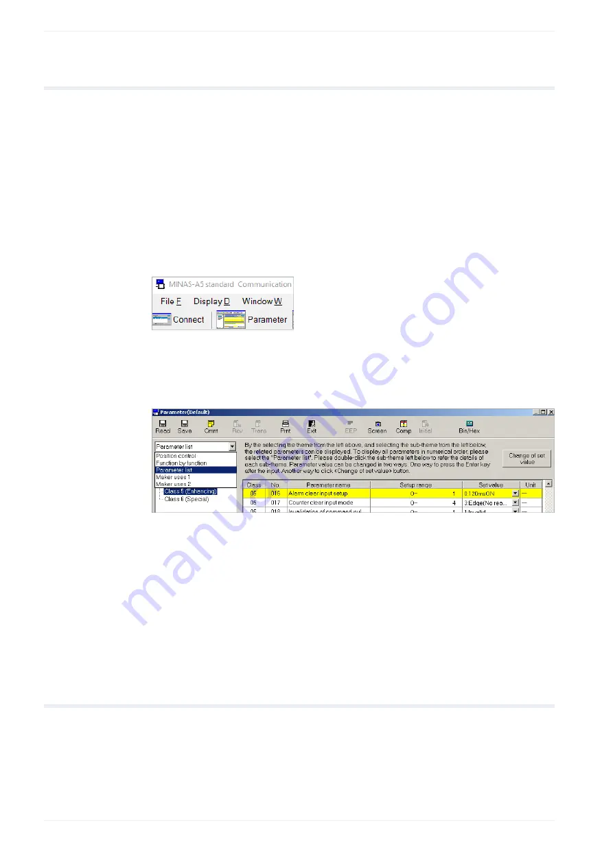
4. Select the “Parameter” tab.

5. In the “Selection of parameter to be read” dialog, select “Read the default”. There is

a message if the parameter values in the servo driver are not the default values. To
overwrite the parameters in the servo driver, select the “Trans” icon.

6. Select the parameter list for your type of servo driver.

7. To change a parameter setting, select the desired parameter class and enter a value.

For parameter descriptions, please refer to the Operating Instructions. You can find
each parameter by its unique parameter number. The parameter number is written in the
format PrX.YY (X: Class, YY: No.).

8. Depending on the parameter, select the “Trans” or the “EEP” icon to transfer a setting to

the servo driver. For yellow parameters, select the “EEP” icon. The parameters will be
saved in the EEPROM of the servo driver. To activate the settings, you need to restart
the servo driver.
All other parameters are transferred simply by selecting the “Trans” icon.

4.1

Basic parameters overview

There are basic parameters which are associated to position control.

The following table shows the setting range and description of the basic parameters.

12 

QS2000_V1.1_EN

Содержание MINAS A5 Series

Страница 1: ...Servo Drives Quick Start Guide Position control by pulse and direction signals MINAS A5 A5E A6SG A6SF QS2000_V1 1_EN 2019 07 www panasonic electric works com...

Страница 2: ...tinuous improvement of the design and performance of its products Therefore we reserve the right to change the manual product without notice In no event will PEWEU be liable for direct special inciden...

Страница 3: ...5 NPN wiring of the X4 connector 11 4 Make parameter settings in PANATERM 12 4 1 Basic parameters overview 12 4 2 Pr0 00 Motor rotation direction 13 4 3 Pr0 01 Control mode 13 4 4 Pr0 06 Counting dire...

Страница 4: ...led information Click on the following links to download the documents from our Panasonic Download Center Information on wiring position control and parameters Operating Instructions Overall AC Servo...

Страница 5: ...QS5002 PANATERM Fit gain tuning 1 4 Available software The following software is available free of charge in our Panasonic Download Center Click on the link to start the download PC configuration sof...

Страница 6: ...ck operation This Quick Start Guide explains how to wire and configure the servo driver to receive pulses from a PLC Example An FP0H PLC and a MINAS A6SF servo driver are connected to control the driv...

Страница 7: ...preference For detailed information on reducing EMI please refer to Recommendations for EMC compliant wiring of servo drivers and motors 3 2 Connectors of the servo driver XA connector main power con...

Страница 8: ...onnections the preassembled connection cable DV0P0988WP 1 is available Panasonic provides different preassembled connection cables for connecting other PLC types 24V DC 0V DC CCWL CWL Servo Axis 1 2 1...

Страница 9: ...e the following signal inputs and outputs OPC1 pin 1 OPC2 pin 2 PULS2 pin 4 SIGN2 pin 6 Open collector inputs to receive command pulses from a PLC SRV ON pin 29 Servo on input to energize the servo mo...

Страница 10: ...1 2 W VDC 1 5 R 220 10 mA Servo ON input Gain switching input Electronic gear switching input 1 Control mode switching input Damping control switching input 1 Alarm clear input Positive direction ove...

Страница 11: ...tor 4 6 13 35 37 39 29 33 34 36 38 1 2 7 8 9 50 0 Vcc 0 Vcc 24 Vcc 24 Vcc To NPN inputs of PLC From NPN outputs of PLC Connections for limit switches PLC pulse outputs PULS2 SIGN2 GND S RDY ALM INP SR...

Страница 12: ...e the parameters in the servo driver select the Trans icon 6 Select the parameter list for your type of servo driver 7 To change a parameter setting select the desired parameter class and enter a valu...

Страница 13: ...Setting range 0 or 1 The default value is 1 Rotation in CCW direction counterclockwise direction 4 3 Pr0 01 Control mode PANATERM parameter Control mode setting Setting range 0 to 6 The default value...

Страница 14: ...g This is the default setting t2 t2 t2 t3 t2 Positive set point value Negative set point value 0 or 2 2 phase pulse input Select this pulse input mode if an encoder or encoder output is used t1 A B t1...

Страница 15: ...1073741824 Pr0 10 The default value is 0 for Pr0 09 and 10000 for Pr0 10 If Pr0 09 is unequal 0 Pr0 08 will have no effect 4 8 Pr5 32 Maximum pulse input frequency PANATERM parameter Command pulse in...

Страница 16: ...NATERM to make the pin assignment 1 Connect your PC to the servo driver 2 Start the PANATERM configuration software 3 Select Other Pin Assign The current pin assignment is uploaded from the servo driv...

Страница 17: ...s if you have any questions or if you have any suggestions for improvement In that case we ask you to include the Quick Start Guide number in the email subject line You can find the number starting wi...

Страница 18: ...7 Record of changes 7 Record of changes QS2000_V1 1_EN 2019 07 Updated links Minor improvements in layout and text QS2000_V1 0_EN 2019 01 First edition 18 QS2000_V1 1_EN...

Страница 19: ...del Commercio 3 5 Z I Ferlina 37012 Bussolengo VR Tel 39 0456752711 Fax 39 0456700444 www panasonic electric works it Nordic Countries Panasonic Electric Works Europe AG Panasonic Fire Security Europe...

Отзывы: