70
KX-TG6051BXM/KX-TGA601BXM
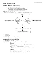
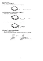
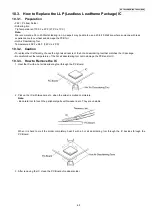
10.3.4. How to Install the IC
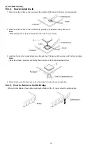
1. Place the solder a little on the land where the radiation GND pad on IC bottom is to be attached.
2. Place the solder a little on the land where IC pins are to be attached, then place the IC.
Note:
• When placing the IC, the positioning should be done very carefully.
3. Heat the IC with a hot air desoldering tool through the P.C.Board until the solder on IC bottom is melted.
Note:
• Be sure to place it precisely, controlling the air volume of the hot air desoldering tool.
4. After soldering, confirm there are no short and open circuits with visual inspection.
10.3.5. How to Remove a Solder Bridge
When a Solder Bridge is found after soldering the bottom of the IC, remove it with a soldering iron.
Содержание KX-TG6051BXM
Страница 2: ...2 KX TG6051BXM KX TGA601BXM ...
Страница 6: ...6 KX TG6051BXM KX TGA601BXM 3 Specifications ...
Страница 24: ...24 KX TG6051BXM KX TGA601BXM 4 8 2 Power Supply Circuit Voltage is supplied separately to each block ...
Страница 30: ...30 KX TG6051BXM KX TGA601BXM 4 10 Signal Route ...
Страница 31: ...31 KX TG6051BXM KX TGA601BXM RF part signal route ...
Страница 36: ...36 KX TG6051BXM KX TGA601BXM 7 1 2 Programming using the Direct Commands ...
Страница 38: ...38 KX TG6051BXM KX TGA601BXM 7 3 Error Messages ...
Страница 39: ...39 KX TG6051BXM KX TGA601BXM 7 4 Troubleshooting ...
Страница 40: ...40 KX TG6051BXM KX TGA601BXM ...
Страница 41: ...41 KX TG6051BXM KX TGA601BXM ...
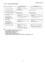
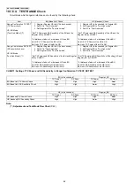
Страница 43: ...43 KX TG6051BXM KX TGA601BXM 8 1 2 TX CW Mode for Base Unit Note 1 Refer to Check Table for RF part P 61 ...
Страница 44: ...44 KX TG6051BXM KX TGA601BXM 8 1 3 RX CW Test Mode for Base Unit Note 1 Refer to Check Table for RF part P 61 ...
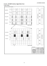
Страница 63: ...63 KX TG6051BXM KX TGA601BXM 10 1 6 5 RF DSP Interface Signal Wave Form Test Burst Mode ...
Страница 64: ...64 KX TG6051BXM KX TGA601BXM Test Burst Mode ...
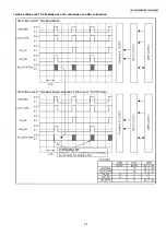
Страница 65: ...65 KX TG6051BXM KX TGA601BXM Test Burst Mode and TX CW Mode when TX confirmation and RX confirmation ...
Страница 72: ...72 KX TG6051BXM KX TGA601BXM ...
Страница 73: ...73 KX TG6051BXM KX TGA601BXM 11 1 2 Handset ...
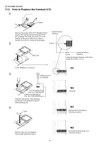
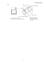
Страница 74: ...74 KX TG6051BXM KX TGA601BXM 11 2 How to Replace the Handset LCD ...
Страница 75: ...75 KX TG6051BXM KX TGA601BXM ...
Страница 87: ...87 KX TG6051BXM KX TGA601BXM Memo ...
Страница 92: ...92 KX TG6051BXM KX TGA601BXM Memo ...
Страница 96: ...96 KX TG6051BXM KX TGA601BXM Memo ...
Страница 100: ...100 KX TG6051BXM KX TGA601BXM Memo ...
Страница 106: ...106 KX TG6051BXM KX TGA601BXM 15 3 Explanation of IC Terminals RF Part 15 3 1 IC701 ...
Страница 107: ...107 KX TG6051BXM KX TGA601BXM 15 3 2 IC801 ...
Страница 108: ...108 KX TG6051BXM KX TGA601BXM 15 4 Terminal Guide of the ICs Transistors and Diodes 15 4 1 Base Unit 15 4 2 Handset ...
Страница 109: ...109 KX TG6051BXM KX TGA601BXM 16 Exploded View and Replacement Parts List 16 1 Cabinet and Electrical Parts Base Unit ...
Страница 111: ...111 KX TG6051BXM KX TGA601BXM 16 3 Accessories and Packing Materials ...


