3
KX-TG6051BXM/KX-TGA601BXM
TABLE OF CONTENTS
PAGE
PAGE
1 Safety Precautions
-----------------------------------------------
1.1. For Service Technicians --------------------------------- 4
2 Warning
--------------------------------------------------------------
2.1. Battery Caution--------------------------------------------- 4
2.2. About Lead Free Solder (PbF: Pb free)-------------- 4
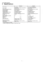
3 Specifications
-----------------------------------------------------
4 Technical Descriptions
-----------------------------------------
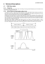
4.1. FHSS Description ----------------------------------------- 7
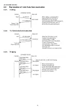
4.2. Explanation of Link Data Communication ----------10
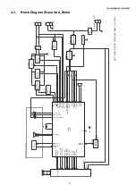
4.3. Block Diagram (Base Unit_Main)---------------------11
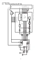
4.4. Block Diagram (Base Unit_RF Part) -----------------12
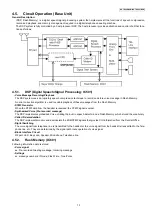
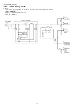
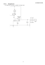
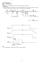
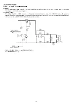
4.5. Circuit Operation (Base Unit)--------------------------13
4.6. Block Diagram (Handset)-------------------------------21
4.7. Block Diagram (Handset_RF Part)-------------------22
4.8. Circuit Operation (Handset)----------------------------23
4.9. Circuit Operation (RF Part)-----------------------------27
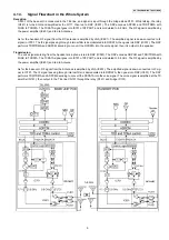
4.10. Signal Route -----------------------------------------------30
5 Location of Controls and Components
------------------
5.1. Controls -----------------------------------------------------32
5.2. Display ------------------------------------------------------32
6 Installation Instructions
---------------------------------------
6.1. Setting Up the Base Unit -------------------------------33
6.2. Battery Installation/Replacement ---------------------33
6.3. Battery Charge --------------------------------------------34
7 Operation Instructions
-----------------------------------------
7.1. Programmable Settings ---------------------------------35
7.2. Dial Lock ----------------------------------------------------37
7.3. Error Messages -------------------------------------------38
7.4. Troubleshooting-------------------------------------------39
8 Test Mode
----------------------------------------------------------
8.1. Adjustment and Test Mode Flow Chart -------------42
9 Service Mode
-----------------------------------------------------
9.1. How to Clear User Setting------------------------------52
10 Troubleshooting Guide
----------------------------------------
10.1. Troubleshooting Flowchart -----------------------------54
10.2. How to Replace the Flat Package IC ----------------67
10.3. How to Replace the LLP (Leadless Leadframe
Package) IC------------------------------------------------69
11 Disassembly and Assembly Instructions
---------------
11.1. Disassembly Instructions -------------------------------71
11.2. How to Replace the Handset LCD -------------------74
11.3. Antenna Soldering Work--------------------------------76
12 Measurements and Adjustments
---------------------------
12.1. Things to Do after Replacing IC or X’tal ------------77
12.2. Base Unit Reference Drawing-------------------------78
12.3. Handset Reference Drawing---------------------------79
12.4. Frequency Table ------------------------------------------80
13 Schematic Diagram
---------------------------------------------
13.1. For Schematic Diagram---------------------------------81
13.2. Schematic Diagram (Base Unit_Main) --------------82
13.3. Schematic Diagram (Base Unit_RF Part) ----------84
13.4. Schematic Diagram (Base Unit_Operation) -------86
13.5. Schematic Diagram (Handset_Main) ----------------88
13.6. Schematic Diagram (Handset_RF Part) ------------90
14 Printed Circuit Board
-------------------------------------------
14.1. Circuit Board (Base Unit_Main)-----------------------93
14.2. Circuit Board (Base Unit_RF Part) -------------------95
14.3. Circuit Board (Base Unit_Operation) ----------------97
14.4. Circuit Board (Base Unit_Antenna)------------------ 99
14.5. Circuit Board (Handset_Main) ---------------------- 101
14.6. Circuit Board (Handset_RF Part) ------------------ 103
15 Appendix Information of Schematic Diagram
-------
15.1. CPU Data (Base Unit) -------------------------------- 104
15.2. CPU Data (Handset) ---------------------------------- 105
15.3. Explanation of IC Terminals (RF Part) ------------ 106
15.4. Terminal Guide of the ICs, Transistors and
Diodes ---------------------------------------------------- 108
16 Exploded View and Replacement Parts List
---------
16.1. Cabinet and Electrical Parts (Base Unit) --------- 109
16.2. Cabinet and Electrical Parts (Handset)------------110
16.3. Accessories and Packing Materials ---------------- 111
16.4. Replacement Parts List--------------------------------112
Содержание KX-TG6051BXM
Страница 2: ...2 KX TG6051BXM KX TGA601BXM ...
Страница 6: ...6 KX TG6051BXM KX TGA601BXM 3 Specifications ...
Страница 24: ...24 KX TG6051BXM KX TGA601BXM 4 8 2 Power Supply Circuit Voltage is supplied separately to each block ...
Страница 30: ...30 KX TG6051BXM KX TGA601BXM 4 10 Signal Route ...
Страница 31: ...31 KX TG6051BXM KX TGA601BXM RF part signal route ...
Страница 36: ...36 KX TG6051BXM KX TGA601BXM 7 1 2 Programming using the Direct Commands ...
Страница 38: ...38 KX TG6051BXM KX TGA601BXM 7 3 Error Messages ...
Страница 39: ...39 KX TG6051BXM KX TGA601BXM 7 4 Troubleshooting ...
Страница 40: ...40 KX TG6051BXM KX TGA601BXM ...
Страница 41: ...41 KX TG6051BXM KX TGA601BXM ...
Страница 43: ...43 KX TG6051BXM KX TGA601BXM 8 1 2 TX CW Mode for Base Unit Note 1 Refer to Check Table for RF part P 61 ...
Страница 44: ...44 KX TG6051BXM KX TGA601BXM 8 1 3 RX CW Test Mode for Base Unit Note 1 Refer to Check Table for RF part P 61 ...
Страница 63: ...63 KX TG6051BXM KX TGA601BXM 10 1 6 5 RF DSP Interface Signal Wave Form Test Burst Mode ...
Страница 64: ...64 KX TG6051BXM KX TGA601BXM Test Burst Mode ...
Страница 65: ...65 KX TG6051BXM KX TGA601BXM Test Burst Mode and TX CW Mode when TX confirmation and RX confirmation ...
Страница 72: ...72 KX TG6051BXM KX TGA601BXM ...
Страница 73: ...73 KX TG6051BXM KX TGA601BXM 11 1 2 Handset ...
Страница 74: ...74 KX TG6051BXM KX TGA601BXM 11 2 How to Replace the Handset LCD ...
Страница 75: ...75 KX TG6051BXM KX TGA601BXM ...
Страница 87: ...87 KX TG6051BXM KX TGA601BXM Memo ...
Страница 92: ...92 KX TG6051BXM KX TGA601BXM Memo ...
Страница 96: ...96 KX TG6051BXM KX TGA601BXM Memo ...
Страница 100: ...100 KX TG6051BXM KX TGA601BXM Memo ...
Страница 106: ...106 KX TG6051BXM KX TGA601BXM 15 3 Explanation of IC Terminals RF Part 15 3 1 IC701 ...
Страница 107: ...107 KX TG6051BXM KX TGA601BXM 15 3 2 IC801 ...
Страница 108: ...108 KX TG6051BXM KX TGA601BXM 15 4 Terminal Guide of the ICs Transistors and Diodes 15 4 1 Base Unit 15 4 2 Handset ...
Страница 109: ...109 KX TG6051BXM KX TGA601BXM 16 Exploded View and Replacement Parts List 16 1 Cabinet and Electrical Parts Base Unit ...
Страница 111: ...111 KX TG6051BXM KX TGA601BXM 16 3 Accessories and Packing Materials ...


