69
KX-TG6051BXM/KX-TGA601BXM
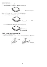
10.3. How to Replace the LLP (Leadless Leadframe Package) IC
10.3.1. Preparation
• PbF (: Pb free) Solder
• Soldering Iron
Tip Temperature of 700
°
F ± 20
°
F (370
°
C ± 10
°
C)
Note:
We recommend a 30 to 40 Watt soldering iron. An expert may be able to use a 60 to 80 Watt iron where someone with less
experience could overheat and damage the PCB foil.
• Hot Air Desoldering Tool
Temperature: 608
°
F ± 68
°
F (320
°
C ± 20
°
C)
10.3.2. Caution
• To replace the IC efficiently, choose the right sized nozzle of the hot air desoldering tool that matches the IC package.
• Be careful about the temperature of the hot air desoldering tool not to damage the PCB and/or IC.
10.3.3. How to Remove the IC
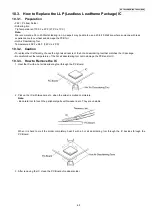
1. Heat the IC with a hot air desoldering tool through the P.C.Board.
2. Pick up the IC with tweezers, etc. when the solder is melted completely.
Note:
• Be careful not to touch the peripheral parts with tweezers, etc. They are unstable.
When it is hard to melt the solder completely, heat it with a hot air desoldering tool through the IC besides through the
P.C.Board.
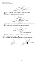
3. After removing the IC, clean the P.C.Board of residual solder.
Содержание KX-TG6051BXM
Страница 2: ...2 KX TG6051BXM KX TGA601BXM ...
Страница 6: ...6 KX TG6051BXM KX TGA601BXM 3 Specifications ...
Страница 24: ...24 KX TG6051BXM KX TGA601BXM 4 8 2 Power Supply Circuit Voltage is supplied separately to each block ...
Страница 30: ...30 KX TG6051BXM KX TGA601BXM 4 10 Signal Route ...
Страница 31: ...31 KX TG6051BXM KX TGA601BXM RF part signal route ...
Страница 36: ...36 KX TG6051BXM KX TGA601BXM 7 1 2 Programming using the Direct Commands ...
Страница 38: ...38 KX TG6051BXM KX TGA601BXM 7 3 Error Messages ...
Страница 39: ...39 KX TG6051BXM KX TGA601BXM 7 4 Troubleshooting ...
Страница 40: ...40 KX TG6051BXM KX TGA601BXM ...
Страница 41: ...41 KX TG6051BXM KX TGA601BXM ...
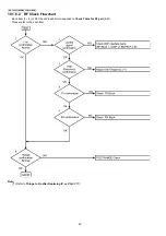
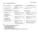
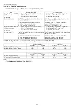
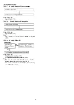
Страница 43: ...43 KX TG6051BXM KX TGA601BXM 8 1 2 TX CW Mode for Base Unit Note 1 Refer to Check Table for RF part P 61 ...
Страница 44: ...44 KX TG6051BXM KX TGA601BXM 8 1 3 RX CW Test Mode for Base Unit Note 1 Refer to Check Table for RF part P 61 ...
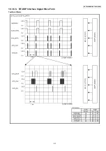
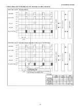
Страница 63: ...63 KX TG6051BXM KX TGA601BXM 10 1 6 5 RF DSP Interface Signal Wave Form Test Burst Mode ...
Страница 64: ...64 KX TG6051BXM KX TGA601BXM Test Burst Mode ...
Страница 65: ...65 KX TG6051BXM KX TGA601BXM Test Burst Mode and TX CW Mode when TX confirmation and RX confirmation ...
Страница 72: ...72 KX TG6051BXM KX TGA601BXM ...
Страница 73: ...73 KX TG6051BXM KX TGA601BXM 11 1 2 Handset ...
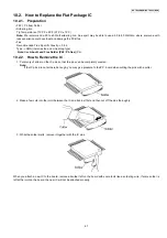
Страница 74: ...74 KX TG6051BXM KX TGA601BXM 11 2 How to Replace the Handset LCD ...
Страница 75: ...75 KX TG6051BXM KX TGA601BXM ...
Страница 87: ...87 KX TG6051BXM KX TGA601BXM Memo ...
Страница 92: ...92 KX TG6051BXM KX TGA601BXM Memo ...
Страница 96: ...96 KX TG6051BXM KX TGA601BXM Memo ...
Страница 100: ...100 KX TG6051BXM KX TGA601BXM Memo ...
Страница 106: ...106 KX TG6051BXM KX TGA601BXM 15 3 Explanation of IC Terminals RF Part 15 3 1 IC701 ...
Страница 107: ...107 KX TG6051BXM KX TGA601BXM 15 3 2 IC801 ...
Страница 108: ...108 KX TG6051BXM KX TGA601BXM 15 4 Terminal Guide of the ICs Transistors and Diodes 15 4 1 Base Unit 15 4 2 Handset ...
Страница 109: ...109 KX TG6051BXM KX TGA601BXM 16 Exploded View and Replacement Parts List 16 1 Cabinet and Electrical Parts Base Unit ...
Страница 111: ...111 KX TG6051BXM KX TGA601BXM 16 3 Accessories and Packing Materials ...

