100
KX-FP701LA
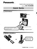
12.5.3. Troubleshooting Items Table
ITEM
SYMPTOM
REFERENCE
ADF
(Auto Document Feeder)
The document does not feed.
See
12.5.4.1.No Document Feed
(
P.102
)
Document jam
See
12.5.4.2.Document Jam
(
P.103
)
Multiple feed
See
12.5.4.3.Multiple Document Feed
(
P.104
)
Skew
See
12.5.4.4.Document Skew
(
P.105
)
Recording paper feed
The recording paper does not feed.
See
12.5.4.5.The Recording Paper does not Feed
(
P.106
)
Paper jam
See
12.5.4.6.Paper Jam
(
P.107
)
Multiple feed and skew
See
12.5.4.7.Recording Paper Multiple Feed and Skew
(
P.108
)
Printing
The sent fax data is skewed.
See
12.5.4.8.The Sent Fax Data is Skewed
(
P.108
)
The received fax data is skewed.
See
12.5.4.9.The Received Fax Data is Skewed
(
P.108
)
The received or copied data is expanded.
See
12.5.4.10.Received or Copied Data is Expanded
(
P.109
)
A black page is copied.
See
12.5.4.11.A Blank Page is Copied
(
P.110
)
A blank page is received.
See
12.5.4.12.A Blank Page is Received
(
P.112
)
Black or white vertical line
See
12.5.4.13.Black or White Vertical Line
(
P.112
)
Black or white lateral line on print out
See
12.5.4.14.Black or White Lateral Line on Print Out
(
P.113
)
An abnormal image is printed
See
12.5.4.15.An Abnormal Image is Printed
(
P.114
)
Communication
FAX, TEL
(Analog board)
Cannot communicate by fax.
An error code is displayed.
See
12.3.2.Communication Section
(P.87) and
Journal
Report
(P.74)
Cannot talk.
The DTMF tone doesn’t work.
The handset / monitor doesn’t work, etc.
See
12.5.6.Analog Board Section
(
P.122
)
Operation panel
Keys are not accepted.
See
12.5.8.Operation Panel Section
(
P.127
)
Sensor
If the electric circuit is the cause, the error
message corresponding to the sensor will
be displayed.
See
12.5.9.Sensor Section
(
P.128
)
Содержание KX-FP701LA
Страница 9: ...9 KX FP701LA 4 General Introduction 4 1 Error Message 4 1 1 Display 4 1 2 Report ...
Страница 11: ...11 KX FP701LA 6 Technical Descriptions 6 1 Connection Diagram ...
Страница 13: ...13 KX FP701LA 6 2 1 General Block Diagram ...
Страница 15: ...15 KX FP701LA 6 3 2 Memory Map ...
Страница 24: ...24 KX FP701LA 6 4 2 Block Diagram ...
Страница 26: ...26 KX FP701LA ...
Страница 41: ...41 KX FP701LA b Redundancy Compression Process Coding Mode This unit uses one dimensional MH format ...
Страница 68: ...68 KX FP701LA 11 2 2 Service Mode Settings Note The above values are the default values ...
Страница 75: ...75 KX FP701LA Countermeasure ...
Страница 76: ...76 KX FP701LA REFERENCE 10Test Mode P 60 ...
Страница 77: ...77 KX FP701LA REFERENCE 10Test Mode P 60 ...
Страница 78: ...78 KX FP701LA REFERENCE 10Test Mode P 60 ...
Страница 79: ...79 KX FP701LA REFERENCE 10Test Mode P 60 ...
Страница 80: ...80 KX FP701LA ...
Страница 81: ...81 KX FP701LA ...
Страница 82: ...82 KX FP701LA REFERENCE 10Test Mode P 60 ...
Страница 86: ...86 KX FP701LA ...
Страница 111: ...111 KX FP701LA ...
Страница 118: ...118 KX FP701LA I O and Pin No Diagram ...
Страница 120: ...120 KX FP701LA Other NG example while the power is ON and the LCD displays the following ...
Страница 121: ...121 KX FP701LA 12 5 5 2 NG Example ...
Страница 125: ...125 KX FP701LA 12 5 7 2 Troubleshooting Flow Chart ...
Страница 129: ...129 KX FP701LA 12 5 9 5 Check the HOOK Switch SW101 ...
Страница 130: ...130 KX FP701LA 12 5 10 CIS Contact Image Sensor Section REFERENCE 1 10Test Mode P 60 Refer to 6 4 4 Scanning Block P 27 ...
Страница 131: ...131 KX FP701LA 12 5 11 Thermal Head Section Note Refer to 6 4 3 Thermal Head P 25 ...
Страница 132: ...132 KX FP701LA 13 Service Fixture Tools ...
Страница 135: ...135 KX FP701LA 14 2 DISASSEMBLY PROCEDURE 14 2 1 HOW TO REMOVE THE PAPER TRAY AND RECORDING PAPER SUPPORT ...
Страница 136: ...136 KX FP701LA 14 2 2 HOW TO REMOVE THE OPERATION PANEL BLOCK ...
Страница 137: ...137 KX FP701LA 14 2 3 HOW TO REMOVE THE OPERATION BOARD AND LCD ...
Страница 138: ...138 KX FP701LA 14 2 4 HOW TO REMOVE THE SEPARATION HOLDER AND EXIT ROLLER ...
Страница 139: ...139 KX FP701LA 14 2 5 HOW TO REMOVE THE IMAGE SENSOR CIS ...
Страница 140: ...140 KX FP701LA 14 2 6 HOW TO REMOVE THE THERMAL HEAD ...
Страница 141: ...141 KX FP701LA 14 2 7 HOW TO REMOVE THE PLATEN ROLLER AND BACK COVER ...
Страница 142: ...142 KX FP701LA 14 2 8 HOW TO REMOVE THE PICKUP ROLLER ...
Страница 143: ...143 KX FP701LA 14 2 9 HOW TO REMOVE THE CASSETTE LEVER ...
Страница 144: ...144 KX FP701LA 14 2 10 HOW TO REMOVE THE BOTTOM FRAME ...
Страница 145: ...145 KX FP701LA 14 2 11 HOW TO REMOVE THE DIGITAL ANALOG SENSOR BOARDS ...
Страница 146: ...146 KX FP701LA 14 2 12 HOW TO REMOVE THE POWER SUPPLY BOARD AND AC CORD ...
Страница 147: ...147 KX FP701LA 14 2 13 HOW TO REMOVE THE MOTOR BLOCK AND SEPARATION ROLLER ...
Страница 148: ...148 KX FP701LA 14 2 14 HOW TO REMOVE THE GEARS OF MOTOR BLOCK ...
Страница 149: ...149 KX FP701LA 14 2 15 INSTALLATION POSITION OF THE LEAD WIRES ...
Страница 163: ...163 KX FP701LA 16 1 4 Power Supply Board 16 1 5 Interface Board ...
Страница 166: ...166 KX FP701LA 16 3 Test Chart 16 3 1 ITU T No 1 Test chart ...
Страница 167: ...167 KX FP701LA 16 3 2 ITU T No 2 Test Chart ...
Страница 168: ...168 KX FP701LA 16 3 3 Test Chart ...
Страница 169: ...169 KX FP701LA MEMO ...
Страница 180: ...180 KX FP701LA MEMO ...
Страница 188: ...188 KX FP701LA MEMO ...
Страница 194: ...194 KX FP701LA 20 1 2 Operation Panel Section ...
Страница 195: ...195 KX FP701LA 20 1 3 Back Cover Section ...
Страница 196: ...196 KX FP701LA ...
Страница 197: ...197 KX FP701LA 20 1 4 Upper Cabinet Section ...
Страница 198: ...198 KX FP701LA 20 1 5 Lower Cabinet Section ...
Страница 199: ...199 KX FP701LA 20 1 6 Gear Block Section ...
Страница 200: ...200 KX FP701LA 20 1 7 Screws ...
Страница 201: ...201 KX FP701LA 20 1 8 Accessories and Packing Materials ...